


Types P341, P342, P389, and P631
2
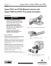
Type P631—Pneumatic actuator that allows remote opening
and closing of the valve.
Pressure source for Type P631: 20 psig (1,4 bar) minimum to
40 psig (2,76 bar) maximum air. Recommended 20 to 25 psig
(1,4 to 1,7 bar).
Installation
!
WARNING
If the Type C407-10 valve is installed in
a pressurized tank, insure that the line
pressure is 0 psi (0 bar) prior to beginning
installation of Type P341, P342, P389, or
P631. Failure to depressurize the line could
result in personal injury.
Ref: MCK-1172—Instruction manual for Type C407-10
internal valve.
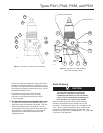
Remote Release—(See Figure 5). To install the Type P341
or P342 latch mechanism, rst remove the operating lever
(key 18) and take off the cover plate (key 56) by removing
the two cap screws (key 17). The new cover plate/latch
assembly can be attached to the valve with the same cap
screws. Tighten the screws to 25 or 30 inch-pounds
(2,8 or 3,5 N•m) torque.
A cable must be run from the pull ring(s) (key 7) on the
Type P341 or P342 to the release handle (Type P650 or
P651 can be used) located at a remote point. The
Type P342 allows two cables to be run in different directions
to two remote locations without additional pulleys. The
cable must be taut for proper operation, and the hookup
may require sufcient pulleys to keep the cable away from
the side of the tank. Pulling the release handle allows the
manual operating lever to return to the closed position. The
fusible link in the mechanism will melt if exposed to re,
allowing the valve to close.
When closing the valve manually, pull back on the pull ring
(key 7) attached to the release mechanism to permit the
valve lever to close.
!
WARNING
Since there is strong spring force on the
operating lever, avoid getting in the way of
the lever as it moves to the closed position.
Failure to do so could result in personal injury.
Air Operation —Type P631 cylinder actuators can be installed
on the valves to provide remote air operation. Minimum
operating pressure for the cylinder is 20 psig (1,4 bar);
maximum cylinder pressure is 100 psig (6,9 bar).
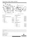
Remove downstream pressure. There must be no
downstream pressure in the Type C407-10 internal valve
while installing the Type P631 air cylinder. To install the
Type P631, (refer to Figure 4 for Type C407-10 Internal
Valve and Figure 6 for Type P631), rst remove the manual
operating lever (key 18) and the cotter pin (key 19). Take
off the cover plate (key 56) by removing the two cap screws
(key 17). Place the Type P631 actuator on the valve. Insert
the operating lever into the Type C407-10 stem with the
cotter pin (key 19). Then secure Type P631 with the two cap
screws (key 17), tightening them to 25 to 30 inch-pounds
(2,8 or 3,5 N•m) torque.
After installing the unit, operate the cylinder with pressure
to see that it smoothly opens and closes the internal valve
without sticking or jamming.
Air Operation—Type P389 cylinder actuators can be installed
on the valves to provide remote air operation. Minimum
operating pressure for the cylinder is 60 psig (4,14 bar);
maximum cylinder pressure is 250 psig (17,2 bar).
Remove downstream pressure. There must be no
downstream pressure in the Type C407-10 internal valve
while installing the Type P389 air cylinder. To install the
Type P389, (refer to Figures 4 and/or 7), rst remove the
manual operating lever (key 18). Take off the cover plate
(key 56) by removing the cap screws (key 17). Place the
Type P389 actuator on the valve and secure it with the two
cap screws (key 17), tightening them to 25 to 30 inch-pounds
(3 or 3,5 N•m) torque. Insert the operating lever (key 18)
through the clevis assembly between the roller and the
clevis pin. Secure the operating lever (key 18) to the
Type C407-10 stem with the cotter pin (key 19). Loosen the
clevis on the cylinder rod and adjust it so that there is some
small movement of the operating lever before it begins to
open the internal valve. Tighten the clevis nut to hold the
clevis at this position. Connect the actuating pressure line
tubing to the end of the cylinder. The operating lever should
not rub on the side of the clevis.
Maintenance
A simple preventive maintenance program for the valve and
its controls will eliminate a lot of potential problems. Fisher
®
recommends these steps be conducted once a month:
1. Regularly inspect the operating lever to see that it
operates freely and that there is no leakage
around the stub shaft. If there is leakage or
sticking, the packing should be replaced.
2. Check for tight closure of the seat disks regularly.
Any leakage indicates a defect in the seat
caused from wear or from dirt or scale lodging
and embedding the seat. To check for leakage,
close the internal valve and exhaust downstream
pressure. Close the rst valve downstream from
the internal valve, and note any pressure build-up
by means of a pressure gauge. If leakage is
indicated, the seat disks should be replaced.
3. Because the Type P389 actuator has a diaphragm
seal, internal lubrication is not required. Periodic
lubrication of the operating lever/cylinder rod pivot
is recommended.