


©2006 Edelbrock Corporation
Rev. 7/06 - BC/mc
Catalog #R09783
Brochure #63-R09783
Page 2 of 2
Edelbrock Corporation, 2700 California Street, Torrance, CA 90503
Toll-Free Tech Line: 1-800-416-8628
Tech E-Mail: Edelbrock@Edelbrock.com
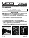
7. Route hoses behind forks and pull out between front fairing and fender. Install supplied cushion clamp over both
hoses so that mounting hole is to left and clamp/hoses are offset to front. Place horn bracket over hoses. Attach
hoses to bracket by inserting factory junction block bolt through cushion clamp and supplied nylon spacer and
threading into factory junction block mounting hole
(See Fig. 4, shown installed on fork tree, top view)
.
Leave bolt finger-tight. Re-install horn to bracket.
8. Route hoses behind front fairing and re-install horn bracket/dust shield assembly to fork tree.
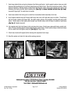
9. Insert supplied double banjo bolt through both banjo hose ends, with right-side banjo on bottom. Thread banjo
bolt into master cylinder until finger-tight. Re-install master cylinder onto handlebar, orienting with mark made
earlier. Orient hoses so that banjos point forward over throttle cables, with left banjo to outside of right banjo
(See Fig. 5)
. Tighten banjo bolt.
10. Use supplied cable tie to hold hoses to fork just above fork clamp. Route hoses underneath factory plastic hold-
down. Pull any remaining slack in hoses down through cushion clamp. Orient cushion clamp so hoses and clamp
do not contact horn and tighten clamp bolt
(See Fig. 6)
. Plug in horn.
11. Check hose clearance throughout entire steering and suspension travel range.
12. Bleed the system and check for leaks while applying pressure.
Fig. 4
Fig. 5
Fig. 6