


Catalog PN 6527
©2002 Edelbrock Corporation
Page 2 of 3 Rev. 5/02
Disassembly
1. Disconnect battery negative cable from battery.
2. Raise vehicle and support with jackstands.
3. Use penetrating oil on all nuts and bolts to be
removed. This will prevent the possibility of broken or
stripped nuts and bolts.
4. Disconnect and remove O2 sensor ( if equipped).
5. Making sure the converter is cool. Remove exhaust
pipes from manifold and catalytic converter.
6. Remove heat riser valve from right side manifold. Put
aside for re-use.
7. Remove air cleaner system (note position of line and
hose connections).
8. Disconnect A.I.R. (Air Injection Reactor) hose from air
tube check valve on both sides.
9. Remove air conditioner compressor rear support
bracket (if air conditioning equipped).
10. Remove power steering pump support bracket (if
power steering is applicable).
11. Disconnect spark plug wires and remove spark plugs.
12. Disconnect temperature sensor wire.
13. Disconnect and remove vacuum pod from right side
manifold.
14. Remove bolts and exhaust manifolds from top side.
15. Clean exhaust flange surfaces on cylinder heads at
this time.
Assembly - Left Side
s1. Install O2 sensor plug in left side manifold.
2. Install TES flange gasket and one 3/8”-16 x 1” bolt,
lock washer, and flat washer at rearmost bolthole
(leave bolt loose enough to accept TES).
3. Install left side TES manifold from top side.
4. Install all but the front two bolts and washers on left
side (do not tighten at this time).
5. Re-install rear power steering support bracket. Do
not tighten at this time (if vehicle is equipped).
6. On vehicles equipped with long A/C compressor,
install supplied A/C support bracket using supplied
bolts, lock washers, and hardened washers. On
vehicles equipped with short A/C compressor, use
1-1/2” long spacers on front two bolts behind original
A/C bracket, use long 12-point bolts, lock washers,
and hardened washer that are supplied.
7. Align all parts and tighten left side bolts and nuts at
this time.
8. Remove all four spark plug boots and terminals.
9. Replace with 90-degree terminals and boots.
10. Re-install spark plugs and re-connect wires on left
side.
11. Re-install temperature sensor wire to temperature
sensor.
Assembly - Right Side
1. Install TES flange gasket and one 3/8”-16 x 1” bolt,
lock washer and flat washer at rearmost bolthole
(leave bolt loose enough to accept TES).
2. Install right side TES manifold from top side.
3. Install vacuum pod and bracket using bolts and 3/4”
spacers supplied. Install remaining bolts and lock
washers.
4. Align all parts and tighten all right side bolts at this
time.
5. Re-install spark plugs and re-connect wires.
6. Remove A.I.R., check valves from original manifolds
and re-install them on TES. With 3/4” hose supplied
in kit, re-connect all A.I.R. injection hoses at this time.
Crossover Pipe Assembly
1. Install heat riser valve with gasket and connect
actuating rod.
2. Install exhaust pipe assembly using three 3/8” x
2-1/2” hex bolts on right side header and three 3/8”
x 1-1/2” hex bolts on left side header.
3. Check for hose and wiring clearance around headers
and exhaust system.
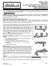
INSTALLATION INSTRUCTIONS