


Catalog #7107, 7109
Rev. 2/06 - RS/mc Page 2 of 2
©2006 Edelbrock Corporation
Brochure #63-0492
• INSTALLATION:
1. Transfer all factory hardware and emissions equipment to the Edelbrock intake manifold.
2. Use only recommended intake gaskets set when installing this intake manifold.
2. Fully clean the cylinder head intake flanges and the engine block end seal surfaces.
3. Attach the intake gaskets to the cylinder head. Make sure the guide pins on the gaskest are aligned with the holes in the intake flanges
of the cylinder heads.
4. Do not use cork or rubber end seals. Use RTV silicone sealer instead. Apply a ¼" high bead across each block end seal surface,
overlapping the intake gasket at the four corners. This method will eliminate end seal slippage. Set manifold assembly on engine.
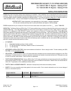
5. Install the intake manifold hold-down bolts. Torque all of the manifold bolts in two steps by the sequence shown in Figure 1 to 25 ft/lbs.
INSTALLATION PROCEDURE
Figure 1 - Chevrolet LT1/LT4 Torque Sequence and Firing Order
Torque Bolts to 25 ft/lbs.; Firing Order: 1-8-4-3-6-5-7-2
• TUNING FOR POWER:
1. Aftermarket tuning may be used with this intake manifold.
3. Use modified or high performance cylinder heads such as our Performer LT1 or Performer LT4.
4. Installation of aftermarket headers, camshafts or both may require ECU tuning, and may affect emissions.
• CAMSHAFT AND HEADERS: Performer RPM Air-Gap manifolds are compatible with aftermarket camshafts and headers. Header primary tube
diameter should be 1-5/8” to 1-3.4” depending on the specific engine combination. Edelbrock has developed a camshaft for use with this intake
manifold on 1992-1997 LT1 engines; Performer RPM #2108 (Will also fit LT4). Please check the catalog or website for rpm and application
guidelines.
Edelbrock Corporation • 2700 California St. • Torrance, CA 90503
Tech-Line: (800) 416-8628 • E-Mail: Edelbrock@Edelbrock.com