


Part #60959, 60969, 60979, 60989
Rev. 1/09 - AJ/mc Page 3 of 4
©2009 Edelbrock Corporation
Brochure #63-0155
INSTALLATION PROCEDURE
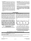
Figure 1 - SBC Cylinder Head Bolt Torque Sequence
Torque Bolts to 65 ft./lbs.
(Torque in 3 steps, gradually approaching final torque spec.)
• Intake Manifold: Although stock Vortec intake manifold will fit,
Edelbrock E-Tec 170 Cylinder Heads are matched in size and
operating range with Edelbrock Performer, Performer RPM, and
Performer RPM Air-Gap Intake Manifolds. Part numbers 2116, 7116
and 7516. 7116, 7516, 2912 and 2913 are recommended for E-Tec
200. Do not use cork or rubber end seals supplied with gaskets. Set
the manifold on the engine with gaskets installed and measure the
gap between the block and the manifold end seal surface. Remove
the manifold and apply enough automotive O2 sensor-safe RTV
silicone sealer to fill the gap along front and rear of block,
overlapping gaskets at the four corners. Follow gasket
manufacturer’s recommendation for the use or non-use of sealant
for the type of intake gasket used. Install manifold and apply Loctite
242 thread locker or equivalent to the intake manifold bolt threads
and torque down to 11 ft./lbs. using the factory specs for torque
sequence.
• Exhaust Headers: Any header or manifold designed for original
equipment Vortec heads will fit Edelbrock E-Tec 170 Cylinder Heads.
E-Tec 200 will require the use of headers suitable for Fel-Pro #1405
(1-3/4” is minimum recommended). Exhaust ports are CNC-profiled
to match Fel-Pro #1404 exhaust gaskets for 6097 or 1405 for 6098,
which are recommended for these applications.
• Spark Plugs: Use 14mm x 3/4” reach gasketed spark plugs. Heat
range may vary by application, but we recommend Champion RC-
12YC (or equivalent) for most street-driven applications. Use anti-
seize on the plug threads to prevent galling in the cylinder
head, and torque to 10 ft./lbs. Do not overtighten
sparkplugs!
Installation is the same as for original equipment cylinder heads. Consult
service manual for specific procedures, if necessary. For 350 c.i.d. and
smaller engines (4.00” bore or less), we recommend Fel-Pro #7733-PT2
head gasket for applications up to 420 HP, #17030 marine gasket for up
to 450 HP and Fel-Pro #1003 beyond that level. Also, GM #10105117 or
Detroit gasket #5565HG. For 400 c.i.d. or larger, Fel-Pro #8364-PT for
moderate horsepower applications, and #1014 for high power
applications. Also, GM #10159455 or Detroit gasket #55431HG. In any
case, for 400 c.i.d. applications, steam holes must be drilled in
cylinder heads as shown in Fig. 2. Be sure that the surface of the
block and the surface of the head are thoroughly cleaned to remove any
oily film before installation. Use alcohol or lacquer thinner on a lint-free
rag to clean. Apply Teflon pipe sealant or suitable sealer to head bolt
threads. Apply 30W oil or suitable lubricant under side of bolt heads and
washers. Torque to 65 ft./lbs. in three steps (40, 55, 65) following the
factory tightening sequence (see Figure 1). A re-torque is recommended
after initial start-up and cool-down (allow 2-3 hours for adequate
cooling).
Fig. 2 - Steam Hole Location for 400 c.i.d. engines only
Drill three 0.125” holes in each head using 400 c.i.d. head gasket as a
guide. Drill only the three lower steam holes (closest to the spark
plugs) as indicated in Fig. 2. Drill straight into the head (90º to the
deck) until drilling breaks through into water jacket (about 5/8”).
COOLANT STEAM HOLES ABSOLUTELY MUST NOT OVERLAP INTO
THE HEAD GASKET SEALING RING (FIRE RING) AREA.
Complete E-Tec cylinder heads #60979 and #60989 are sold with the pushrod guide plates and rocker studs installed, but they will require checking
for proper valve train and pushrod clearance before operating engine.
PUSHROD GUIDE PLATE ALIGNMENT: The pushrod guide plates are attached to the cylinder heads with two (each) rocker studs. There is enough
clearance around the stud holes to adjust the guide plates for optimum alignment of your valve train components.
1. After the heads have been bolted on your engine and torqued to specs, install your pushrods, rocker arms, and rocker arm adjusting
nuts.
SPECIAL INSTRUCTIONS FOR E-TEC ALUMINUM CYLINDER HEADS #60979 & #60989