


Catalog #4754
Rev. 10/06 - RS/mc Page 2 of 4
©2006 Edelbrock Corporation
Brochure #63-0255
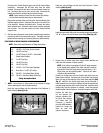
Install the vacuum fittings into the top of the Performer X intake
manifold
(See Fig. 2-B)
.
Install the water outlet fitting into the mounting flange and install the
1/8” NPT x 8mm barb into the water outlet fitting
(See Fig. 2-C)
.
2. Remove Idle air control motor from factory intake manifold and
install onto the Performer X intake manifold
NOTE: If the vehicle is equipped with the IAC motor mounted
on the throttle body instead of the intake manifold, install the
supplied IAC Cover Plate using the two supplied 8mm x 1.25 x
20mm bolts and the supplied gasket. Leave the IAC motor
installed on the throttle body.
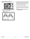
Remove the throttle body, and two throttle body studs from the
factory intake manifold. Using two nuts on each stud, and jamming
them, will help get the studs out of the stock intake manifold
(See
Fig. 3)
. Install the two throttle body studs into the Performer X
intake manifold, one on the upper right bolt hole of the throttle body
mounting flange and one on the lower left bolt hole. Install the stock
throttle body onto the Performer X manifold. Install the supplied
throttle bracket onto the Performer X manifold using the stock bolts.
Remove the stock fuel
rail, fuel injectors, fuel
pressure regulator, fuel-
rail-studs and spacers
and install onto the
Performer X manifold
using the OEM hardware.
Inspect all o-rings and
seals for wear and
replace if necessary.
Disconnect the Throttle Position Sensor and Idle Air Control Motor
connectors. Disconnect the PCV valve hose from the intake
manifold. Disconnect the fuel return line from the steel chassis fuel
line. Disconnect the fuel line from the fuel filter. Disconnect the
coolant lines from the throttle body and manifold flange.
NOTE: Some coolant will drain from the coolant lines leading
into the intake manifold when they are disconnected
.
Remove the two bolts at the rear of the stock manifold attaching the
manifold support bracket. Disconnect the vacuum lines at the rear
of the manifold. Remove the throttle cable. Remove the factory
intake manifold nuts. Remove the stock intake manifold assembly
and set aside. You may now remove the stock intake manifold
support brace.
4. Stuff the open intake ports in the cylinder head with paper towels to
prevent any debris from entering the engine. Thoroughly clean the
gasket surface removing any remaining sealant or gasket material.
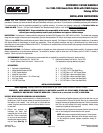
PERFORMER X INTAKE MANIFOLD PREPARATION
NOTE: Refer to the chart below for all Fitting Descriptions.
1.
NOTE: Use anti-seize or teflon paste on the threads of fittings
before installing them into the intake manifold.
Install the vacuum fittings into the underside of the Performer X
intake manifold
(See Fig. 2-A)
.
Fig. 2-A
#1 #2 #3 #4 #5 #6
Fig. 2-B
#8
Fig. 2-C
#10
#9
#1 1/8 NPT x 3/16” Barb (Cruise Control)
#2 1/8 NPT Pipe Plug
#3 1/4 NPT Elbow & 1/4 NPT x 10mm Barb
(Power Brake Booster)
#4 1/4 NPT Pipe Plug
#5 1/8 NPT Pipe Plug
#6 1/8 NPT Pipe Plug
#7 1/8 NPT x 3/16” Barb (Fuel Regulator)
#8 9mm Barb x 1/4 NPT (PCV Valve)
#9 3/8 NPT x 17mm Barb (Water Outlet)
#10 1/8 NPT x 8mm Barb (Water Outlet Tee)
Fitting Description Chart
Fig. 3
#7