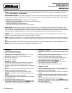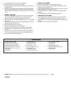
HARDWARE SUPPLIED
• PLEASE complete and mail your warranty card. Be sure to write the model number of this product in the “Part #____” space.
THANK YOU.
1- Manifold left side #25-9005
1- Manifold right side #25-9006
1- Extension pipe left side #25-9505
1- Extension pipe right side #25-9506
3- Spacer tubes; 5/8" O.D. x 1.530" long
1- Spacer tube; 5/8" O.D. x .72" long
1- Donut gasket
1- Muffler clamp
1- O2 sensor pigtail ; 12"
2- Chevy V8 port gaskets
2- Hex bolts; 3/8"-16 x 2"
2- Hex bolts; 3/8"-16 x 3"
2- 12 pt. Ferry bolts; 3/8"-16 x 3"
16- Lock washers; 3/8"
4- Flat washers; 3/8" AN
12- Hex header bolts; 3/8" x 1"
4- 3/8" hardened flat washers
1- Connector flange
1- O2 sensor plug
1- 90Þ Spark plug wire boot
1- 90Þ Spark plug wire terminal end
2- Hose connectors
1- Hose (A.I.R.); 16"
9. Re-install spark plugs and re-connect wires on left side.
10. Change spark plug wire ends and boots as needed.
11. Re-install temperature sensor wire support bracket and re-connect wire to
temperature sensor.
12. Re-install O2 sensor. Use anti-seize on threads of sensor and torque to 30
ft./lbs. Re-route O2 sensor wire from wire loom to O2 sensor making sure
all wires are clear of exhaust system (O2 sensor extension wire is included
in kit).
• ASSEMBLY - RIGHT SIDE
1. Install T.E.S. flange gasket and one 3/8"-16 x 1" bolt, lock washer and flat
washer at rearmost bolt hole (leave bolt loose enough to accept T.E.S.).
2. Install right side T.E.S. manifold and dipstick tube from top side.
3. Install remaining bolts, lock washers, dipstick and tube. Do not tighten bolts
at this time.
4. Re-install O.E.M. front stud bolt with spacer (supplied). Align all parts and
tighten all right side bolts at this time.
5. Re-install spark plugs and re-connect wires.
6. Change spark plug wire ends and boots as needed.
7. Re-install diverter valve assembly in front O.E.M. stud bolt and tighten.
8. Re-connect electrical connections and vacuum lines to diverter valve
assembly.
9. Remove A.I.R. check valves from original manifolds and re-install them on
T.E.S. Re-connect using rubber hose and connectors supplied in this kit.
10. Raise vehicle and support with jackstands.
• CROSSOVER PIPE ASSEMBLY
1. Assemble both lower pipes. Do not clamp tight at this point.
2. Rotate E.F.E. valve 180Þ from its original position (the diaphragm will now
be facing to the rear of the vehicle).
3. Install crossover pipe assembly on vehicle with four 3/8" bolts, lock washers
and gaskets supplied. Do not tighten at this time.
4. Form A.I.R. injection tube to catalytic converter. Align and tighten all bolts
and clamps.
5. Be sure that all brake and fuel lines have adequate clearance.
• LOWER VEHICLE TO THE GROUND
1. Connect negative cable to battery. At this point, it would be a good idea to
look everything over and make sure nothing was missed in assembly.
2. Start vehicle, bring up to normal operating temperature and check for possi-
ble leaks.
3. Turn engine off and let cool. Tighten all bolts again.


