


Page 2
©2003 Edelbrock Corp
Brochure #63-0025
Rev. 1/03
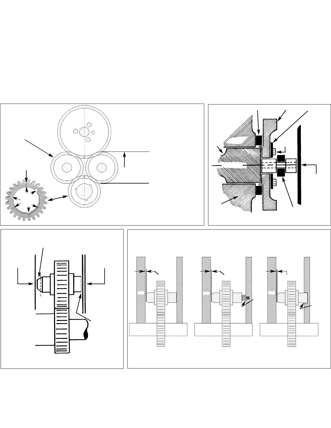
7 With the idler sub-assembly fully installed in mesh with crank and
cam gears and the large idler gear axle all the way back against the
block, check the clearance between end of idler axles and front
cover as follows:
(a) Place a small amount of clay on the front end of both axles as
shown in Figure 3.
(b) Install front cover with gasket in place and tighten cover bolts.
(c) Remove cover and measure the thickness of the compressed
clay. It should be .005"-.030".
(d) If axles are too long and are bottoming out between the block
and the front cover, you will need to grind off material from axles
as noted in Figure 3.
(e) Note: Non-stock timing covers may require special allen-type
screws be installed into the face of the cover to obtain the
correct thrust adjust ment for proper idler shaft clearance.
8. With all gears correctly in mesh and timed, tighten the three camshaft
capscrews to 20 ft./lbs. It would also be a good idea to use Locktite™
or equivalent on the bolt threads prior to final assembly.
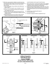
9. Install the front thrust bearing assembly into the center hole of the
camshaft gear. Make sure that the bolt heads of the cam gear bolts do
not protrude farther than the nose of the thrust bearing; grind or file if
necessary.
10. Lubricate all gears and bearings with engine oil.
11. Re-install the front cover.
12. Re-install all components removed in preparation for step 1.
Edelbrock Corporation
2700 California Street
Torrance, CA 90503
Toll-Free Tech Line: 1-800-416-8628
Tech email: edelbrock@edelbrock.com
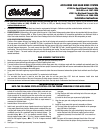
Line up Timing Marks on Shaft
centerline
Reverse idle (20 Teeth) should have
between .005-.070 free vertical
travel with power idler in hard
mesh with cam and crank gears
Power idler (23 teeth)
Figure 1
Figure 4
CrankshaftCrankshaftCrankshaft
.015 -.060 Clearance
Stock Front Cover
Standard Inside Depth
Aluminum Front Cover
Inside Depth more Than
Stock
Aluminum Front Cover
Inside Depth Less Than
Stock
.015 -.060 Clearance
.015 -.060 Clearance
Block
Block
Block
Install
Screw in
Front
Cover to
Touch
Idler
Pins
Mill Recess
in Front Cover
Brass Thrust Ring
Locking Plate
Cam
Block
Block
Crankshaft
Cam Gear
Front Thrust
Bearing Assembly
Capscrew
Timing Cover
Timing Cover
Remove material from
this end of axle.
Place clay in
this area to
check shaft
end clearance
Figure 2
Figure 3
Timing
Mark
A
O
R