


2
10. Connect terminal #1 from the toggle switch to an “ignition-switched” +12 volt source. We
recommend that you connect this wire to the switched-on power of the vehicle’s nitrous system
arming switch. This ensures that the heater can only be activated when the nitrous system is
armed.
11. Connect terminal #2 from the toggle switch to the white wire on the relay.
12. Connect terminal #3 to a good chassis ground.
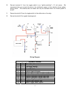
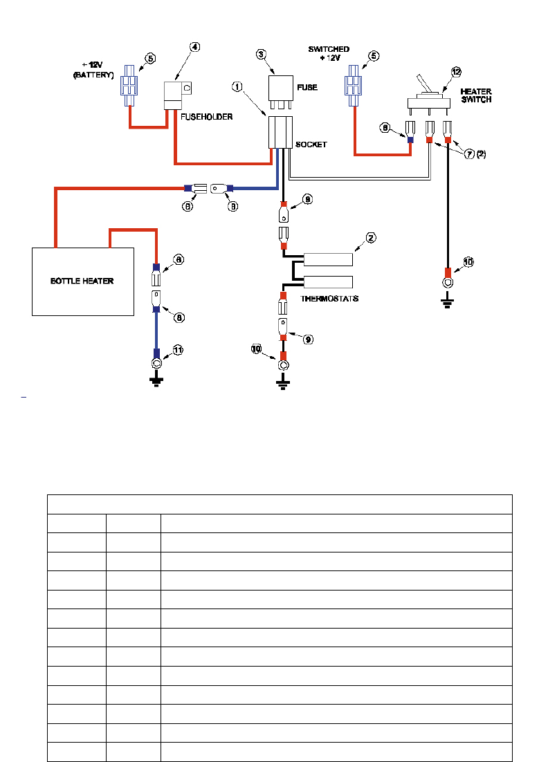
Wiring Diagram
Hardware Includes:
Item Qty. Description
1 1 Nitrous Relay Receptacle
2 1 Thermostat Assembly
3 1 Relay, SPDT, with Diode
4 1 Fuse, ATO, 25 Amp
5 2 Crimp-on Splice Connector
6 3 Crimp-on Disconnect Terminal, Female, Blue
7 2 Crimp-on Disconnect Terminal, Female, Red
8 2 Crimp-on Disconnect Terminal, Male, Blue
9 2 Crimp-on Disconnect Terminal, Male, Red
10 2 Crimp-on Ring Terminal, Red
11 1 Crimp-on Ring Terminal, Blue
12 1 Switch, Toggle, Power, Lighted