


Page 3 of 4
2004 Edelbrock Corporation
Brochure #63-0131
Catalog #72230
Rev. 5/04
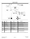
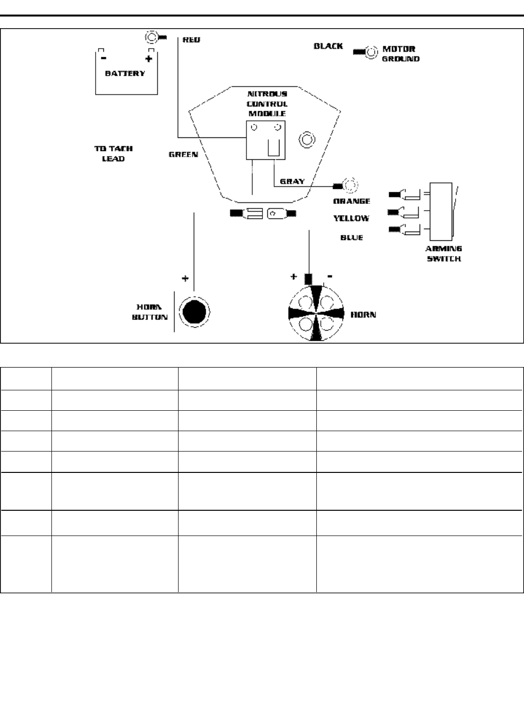
WIRING DIAGRAM
Wire System Origin Destination
Color
Red Battery Voltage Nitrous Module Harness Battery or Key activated circuit breaker
Black Module Ground Nitrous Module Harness Ground to cylinder head bolt
Green Tach Trigger wire Nitrous Module Harness Factory Tachometer lead or Coil
Orange System Arming Wire Nitrous Module Harness Top Terminal of Arming Switch
Yellow Horn interface wire Horn power lead. From Center Terminal of Arming Switch
Harness 12+ factory
Harness lead.
Blue Horn interface wire Horn power lead. From Bottom Terminal of Arming Switch
Horn 12+ Side of Horn
Gray Single or dual fire Nitrous Module Harness SF* Leave wire end loose and tape or
SF/DF Ignition lead cut and apply a butt connector.
DF* Ground wire to Module plate