©2003 Edelbrock Corporation
Rev. 5/03
Brochure No. 63-0165
Catalog #70401
Page 2 of 2
Fuel Pump Installation and Wiring
(Continuation)
5. Connect the remaining cut fuel hose from step 1 to the outlet side of the fuel pump and secure with one of the
supplied hose clamps.
6. Install the supplied Male Push Connect Fitting to the other end of the fuel hose and secure with a supplied hose clamp.
7. Connect the Male Push Connect Fitting on the fuel hose to the Female Push Connect Fitting that you previously
disconnected from the fuel filter.
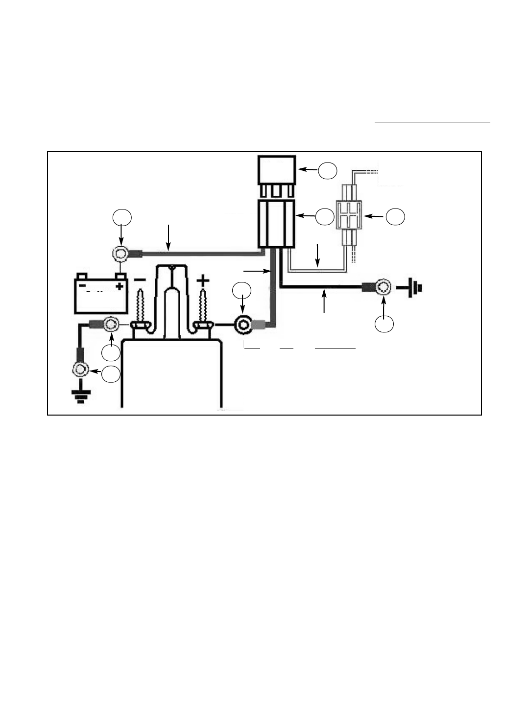
8. Follow the wiring diagram below for installation of your fuel booster pump relay.
10. Check the fuel system for leaks by turning the ignition key to the “On” position. Do not start the engine
. Inspect
all fittings and lines for leaks. Also check the wires from time to time to inspect for fraying or damage to the wires.
Edelbrock Corporation
2700 California Street
Torrance, CA 90503
Tech Line: (800) 416-8628
Office: (310) 781-2222
Tech Fax: (310) 972-2730
Tech E-Mail: edelbrock@edelbrock.com
Fuel Pump Relay Wiring Schematic
RED
BLUE
WHITE
BLACK
1
2 3
4
4
5
5
Item Qty. Description
1 1 30 amp Relay
2 1 Wire Harness
3 1 16/18 Splice Connector
4 3 14/16G 3/8” Ring Terminal, Nylon Ins.
5 2 14/16G Ring Terminal #8 Stud, Nylon Ins.
Fuel Pump
Socket
Relay
Fuel Pump
Wire
Battery
4


