


©2005 Edelbrock Corporation
Rev. 07/05 - DC/mc
Catalog #70057 & #70058
Brochure #63-0331
Edelbrock Corporation
2700 California Street
Torrance, CA 90503
Toll-Free Tech Line: 1-800-416-8628
Tech E-Mail: edelbrock@edelbrock.com
Victor Jr. 5.0L Plate Jet Map
Horsepower Gain Nitrous Jet Fuel Jet
300 HP Please contact the Edelbrock
Tech Line for this jetting.
250 HP 32 24
200 HP 29 22
150 HP 26 20
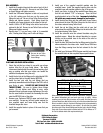
Tighten these
four swivel
adapters into
the same
depth or your
rails may leak.
Be sure to use Teflon
Paste when installing
these fittings.
RAIL ASSEMBLY:
1. Install the 8 supplied plugs into the ends of each of the 4
rails supplied with your kit. Be sure to use Teflon Paste
on these fittings and tighten securely.
2. Install four 3AN swivel adapters in each rail, as pictured
to the left, making sure that you use the same color
fittings for each rail. Be sure to use Teflon Paste on these
fittings and tighten securely. Each fitting should be
threaded in the same distance as the others in that rail.
3. Install a 3AN to 1/8”NPT fitting in the inlet of each rail as
pictured to the left. Be sure to use Teflon Paste on these
fittings and tighten securely.
4. Repeat steps 1-3 so you have a total of 4 assembled
rails, 2 having blue fittings, and 2 with red fittings.
PLATE AND SOLENOID INSTALLATION:
1. Select the jets that you intend to use with your nitrous
system from the jet map listed below. We highly
recommend starting with the small jets and working your
way up making sure that your engine can handle the
additional horsepower along the way.
2. Install the fuel jets in the fittings on the side labeled FUEL
and the nitrous jets in the side labeled NITROUS.
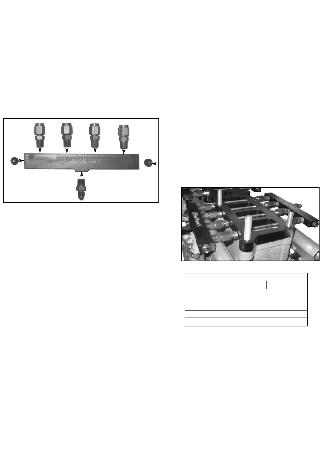
3. Install the two rails with the red fittings that you
previously assembled onto the fittings of the FUEL side of
your Victor Jr. plate. DO NOT USE ANY SEALANT ON
THESE FITTINGS. Be sure to tighten these fittings
evenly. Do not tighten each fitting at once, rotate
between fittings to prevent uneven tightening of the rails.
Use the same method to install the remaining blue rails
onto the NITROUS side of the plate.
4. Remove your Performer RPM (II) upper and studs from
your manifold. Scrape any left over gasket material for
your manifold upper and lower being sure that the
manifold flanges are clean.
5. Install the supplied studs in place of the ones that you
just removed.
When making your jet selection from the chart above, always start with
the lowest horsepower gain and work your way up safely. Before
installing your jets into the jet holders on the plate, hold the jets up to
light and make sure that the hole in the jet is free from obstructions and
there is no debri in the jet. Any kind of blockage in the jet can potentially
cause severe engine damage to your vehicle. Be sure that you install
the nitrous jets in the nitrous fittings and the fuel jets in the fuel fittings.
Each side of your nitrous plate is etched with an “N” for Nitrous or “F”
for Fuel to denote which side requires which jets.
6. Install one of the supplied manifold gaskets onto the
manifold lower. Install the supplied spacer plate onto the
manifold lower with another gasket on top of the spacer.
7. Install your Victor Jr. plate on the manifold lower being sure
that the side labeled “TOP” is facing up. Place the third
supplied gasket on top of the plate. Improperly installing
the plate may cause severe damage to your engine.
8. Install the blue tee fitting into the outlet side of your nitrous
solenoid and the blue 6AN filter fitting into the inlet side of
the nitrous solenoid using Teflon Paste.
9. Install the red tee fitting into the outlet side of your fuel
solenoid and the red 6AN filter fitting into the inlet side of the
fuel solenoid using Teflon Paste.
10. Install the solenoids onto the solenoid brackets using the
supplied screws. Mount the solenoid brackets to a secure
location on the manifold close to the inlets of the rails for
your Victor Jr. plate.
11. Install the blue 3AN lines from the tee fitting coming from the
nitrous solenoid to the nitrous rails. Install the red 3AN lines
from the fittings coming from the fuel solenoid to the fuel
rails.
12. Re-install your Performer RPM (II) upper manifold and torque
the manifold bolts to their required torque specifications.