


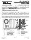

Catalog #70024 & 70025
Brochure No. 63-0182
Page 3 of 4
©2003 Edelbrock Corporation
Rev. 7/03
JET MAP INFORMATION
Edelbrock engineering has conducted dyno testing with the Victor Jr. system to provide jetting maps for two separate
plates at different jetting levels. These jet combinations are supplied with this system to enable you to vary your engine’s
power output. On a typical mildly to highly modified 350 or larger cubic inch engine, you can expect the following
approximate power gains for each of the jetting levels:
DOMINATOR-FLANGE JET MAP
Nitrous/Fuel Jetting Approx. HP Gains Timing Adj.
38/39 200hp 30 Deg. Total
54/54 300hp 24 Deg. Total
61/58 400hp 20 Deg. Total
SQUARE-FLANGE JET MAP
Nitrous/Fuel Jetting Approx. HP Gains Timing Adj.
39/39 200hp 28 Deg. Total
48/46 300hp 24 Deg. Total
58/56 400hp 20 Deg. Total
The dyno tests were conducted at Edelbrock using a mildly modified 500 cubic inch engine. Modifications included
Edelbrock intake manifold, dyno headers and improved ignition. These tests were conducted with 950 psi nitrous
pressure, 7.5 psi fuel pressure, and 110 Octane fuel or better.
The Victor Jr. Series Nitrous Systems are intended for single-plane manifolds only. Do not use a dual-plane intake manifold
with the Victor Jr. Series Nitrous Systems. In testing, we have found that dual-plane manifolds have some distribution
problems at these super high flow rates that could cause serious engine damage.
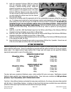
13. Install the assembled Performer RPM Fuel Solenoid
onto the remaining solenoid bracket using the
remaining 2 solenoid mounting screws. Mount this
solenoid and bracket as close to the Victor Jr. Nitrous
Plate as possible on the opposite corner of the other
Performer RPM Fuel Solenoid on the intake manifold.
You may not want to solidly mount the bracket yet until
you have installed the nitrous hoses from the solenoid
tee to the plate fittings.
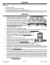
14. Using the jet chart below, select the appropriate jets for the corresponding horsepower setting that you wish to
use. It is always wise to start with a lower horsepower selection and progressively step up to your intended
power setting to be sure that the engine can handle the extreme increase in horsepower. Be sure that you
install the fuel jets in the fuel jet holders and the nitrous is the nitrous jet holders. Failure to install
the jets correctly may cause serious engine damage. Both the fuel and the nitrous inlets to the plate are
etched next to their correct fitting. Be sure not to mix the two up. Above is a picture of a jet being properly
installed.
15. Install the 4 red 3AN x 3AN Steel Braided hoses from the 3AN tee outlet fittings of the Performer RPM Fuel
Solenoids to the Fuel Jet Holders on your Victor Jr. Nitrous Plate.
16. Install the 4 blue 3AN x 3AN Steel Braided hoses from the 3AN tee outlet fittings of the Performer RPM Nitrous
Solenoids to the Nitrous Jet Holders on your Victor Jr. Nitrous Plate.
17. Install the 2 blue 6AN 15 inch Steel Braided hoses from the inlet fittings of the Performer RPM Nitrous Solenoids
to the supplied blue 6AN Tee fitting.
18. Route the 6AN feed line through the same route as your previous 4AN feed line, if possible. Connect one end
of this line to the bottle nut and the other to the blue 6AN Tee Fitting.