


©2004 Edelbrock Corporation
Brochure No. 63-0190 - DC/mc
Rev. 03/04
Catalog #70003 & #70004
Page 18 of 28
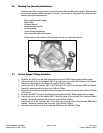
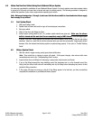
3.3 Nitrous Electrical System Installation Procedures
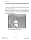
Determine the location of the relay and fuse holder wire harness. Most common installations locate these
components inside the driver’s compartment and close to the fuse panel under the dash. You can also mount the
relay and ruse holder harness close to the battery. However, these connectors are water-resistant not waterproof,
so care is required when mounting this assembly under the hood of your vehicle.
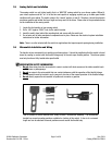
3.4 Nitrous Relay and Fuse Holder Installation
The wire harness attached to the relay and fuse holder includes 8 feet of color-coded wires to make the electrical
system installation for your Edelbrock Nitrous System as easy as possible. We recommend not cutting any lengths
of wires from the wire harness or complete the wiring of the nitrous system until all of the mechanical components
are securely mounted in their permanent locations.
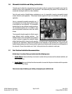
Once all of the solenoids and switches are placed, route the un-cut wires from the harness to each location allowing
enough wire length on each circuit to not interfere with operating linkages, heat sources, brackets, etc. Pay
particular attention to sharp edges along the route of your wire harness to prevent wire damage.
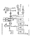
After you have accounted for the routing of your wires, follow the Wire Harness Schematic on page 15 and use the
Origin and Destination Map as a guide for which electrical connectors are used in each circuit.
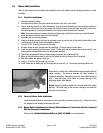
Once you have decided the location of the relay and fuse holder, secure them with fasteners (not included with kit)
such as sheet metal screws, bolts and nuts, etc. Allow for some slack in the red wire that connects the relay and
fuse holders together.
When mounting your relay and fuse holder, make sure the mounting surface is strong enough to support servicing
the relay and fuse. Also, ensure you allow for some slack in the wire that joins the fuse holder to the relay mount.
This will avoid any potential loss of power due to stress on the wire harness.
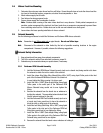
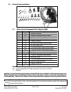
The fuse is covered by the fuse mount housing. The relay for the Performer system is rated for 30 amps, and the
fuse is 15 amps.
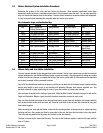
Wire Schematic Origin and Destination Map
Wire Color System Origin Destination Terminal Used
Red Main System Bat. Relay Harness Bat. Volt. Signal Ring
Voltage Arming Switch
Blue 2nd Stage Functions Relay Harness 2nd Stage Solenoids M/F Spades
Yellow 1st Stage Functions Relay Harness 1st Stage Solenoids M/F Spades
Green 2nd Stage Functions Relay Harness 2nd Stage Pushbutton Female Spade
Black 1st Stage Functions Relay Harness Microswitch Female Spade
White Main System Arming Relay Harness Toggle Switch Female Spade
White Main System Arming Relay Harness White Sys. Arm Wire Splice Connector
Red Main System Arming Arming Switch Switched 12V Power 2 F Spades,
Blade Conn.
Black Main System Arming Arming Switch Ground F Spade, Ring
Black 1st Stage Functions Microswitch Ground F Spade, Ring
Black 1st Stage Functions Microswitch Splice Pushbutton Splice, F Spade
Black 1st Stage Functions 1st Stage Solenoids Yellow Wire Male Spade
Black 2nd Stage Functions 2nd Stage Solenoids Blue Wire Male Spade
Black 1st Stage Functions 1st Stage Solenoids Ground Ring Terminal
Black 2nd Stage Functions 2nd Stage Solenoids Ground Ring Terminal