


Catalog #s 68572, 68573, 68582, 68583
©2006 Edelbrock Corporation
Page 2 of 3
Brochure #63-68572
Rev. 6/06 - DA/mc
DISASSEMBLY
1. Disconnect battery negative cable from battery.
2. Raise vehicle and support with jackstands.
3. Use penetrating oil on all nuts and bolts to be
removed. This will prevent the possibility of broken
or stripped nuts and bolts.
4. Making sure the converter is cool, remove the
exhaust crossover pipe.
5. Lower vehicle to the ground.
• DISASSEMBLY - LEFT SIDE
6. Remove air cleaner system (note position of line and
hose connections).
7. Disconnect A.I.R. (air injection reactor) tube from
exhaust manifold (#68582/68583 only).
8. Remove air conditioner compressor rear support
bracket (if air conditioning equipped).
9. Remove power steering pump support bracket (if
power steering is applicable).
10. Disconnect spark plug wires and remove spark
plugs.
11. Remove O2 sensor, being careful not to rupture or
destroy the unit.
WARNING: Do not clean this unit in any cleaning
solvent and do not rupture wire.
12. Disconnect temperature sensor wire.
13. Remove bolts and exhaust manifold from top side.
• DISASSEMBLY - RIGHT SIDE
14. Disconnect A.I.R. injection tube from exhaust
manifold (#68582/68583 only).
15. Disconnect spark plug wires and remove spark
plugs.
16. Remove bolts and exhaust manifold from top side.
17. Clean exhaust flange surfaces on cylinder heads at
this time.
• ASSEMBLY - LEFT SIDE
1. Install T.E.S. flange gasket and one 3/8"-16 x 1" bolt,
lock washer, and flat washer at rearmost bolt hole
(leave bolt loose enough to accept T.E.S.).
2. Install left side T.E.S. manifold from top side.
3. Install all but the front two bolts and washers on left
side (do not tighten at this time).
INSTALLATION INSTRUCTIONS
4. Re-install rear power steering support bracket. Do
not tighten at this time.
5. Re-install rear A/C support bracket with bolts, lock
washers, and spacers supplied.
6. Align all parts and tighten left side bolts and nuts at
this time.
7. Re-install spark plugs and re-connect wires on left
side.
8. Re-install temperature sensor wire to temperature
sensor.
9. Re-install O2 sensor. Use anti-seize on threads of
sensor and torque to 30 ft./lbs. Re-route O2 sensor
wire from wire loom to O2 sensor making sure all
wires are clear of exhaust system (O2 sensor
extension wire is included in kit).
• ASSEMBLY - RIGHT SIDE
1. Install T.E.S. flange gasket and one 3/8"-16 x 1" bolt,
lock washer and flat washer at rearmost bolt hole
(leave bolt loose enough to accept T.E.S.).
2. Install right side T.E.S. manifold from top side.
3. Install remaining bolts, lock washers, and spacer
tube for dipstick to clear exhaust flange.
4. Align all parts and tighten all right side bolts at this
time.
5. Re-install spark plugs and re-connect wires.
6. Remove A.I.R. check valves from original manifolds
and re-install them on T.E.S. With hose supplied in
kit, re-connect all A.I.R. injection hoses at this time
(#68582/68583 only).
7. Raise vehicle and support with jackstands.
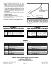
• CROSSOVER PIPE ASSEMBLY
1. Carefully align and tap adapter tube into converter
using a piece of wood or a mallet to protect the end
of the adapter.
NOTE: Be sure adapter goes all the way in,
approximately 2-1/2".
2. Install crossover pipe assembly on vehicle using four
3/8" x 2" bolts with lock washers and donut gaskets
supplied.