


©2001 Edelbrock Corporation
Rev. 5/01
PARTS LIST
DISASSEMBLY (Continued)
5. Remove O2 sensor (if applicable) being careful not to destroy or rupture the unit.
clean this unit in any cleaning solvents and do not rupture
.
6. Remove the two nuts from hanger bracket. Remove the two bolts and springs at the
catalytic converter. Then unbolt the three bolts at the mid-section of manifold and
remove lower portion o -
7. Remove the bolt that is attached to the engine block in the lower section of manifold.
Remove bolts from manifold at cylinder head and pull manifold out from top side.
Note: Save all factory nuts, bolts and springs to be used during re-
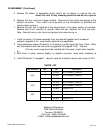
1. Install (a section) of header assembly from top side with gasket and 9 hardened
washers (supplied in kit), using factory bolts/nuts as applicable.
2. Install secondary section (B section) to (A section) top half using the three 10mm. Bolts
and lock washers with the two crush ring gaskets (all supplied in kit). Use anti-
. (The two crush rings should be installed with the seam or split down towards
B-
3. With donut in place, connect header to catalytic converter using stock hardware as
4. Install O2 sensor “if equipped”. Use anti-seize on threads of sensor and torque to 30 ft.
Part Numbers Qty. PN Description
1 25-9180 Pro-Flo Header (A Section)
6637
1 25-9201 Pro-Flo Header (B Section)
1 22-6852 Installation Kit
1 25-9182 Pro-Flo Header (A Section)
6737 1 25-9200 Pro-Flo Header (B Section)
1 22-6852 Installation Kit
1 25-9178 Pro-Flo Header (A Section)
6837 1 25-9199 Pro-Flo Header (B Section)
1 22-6852 Installation Kit
Edelbrock Corporation
2700 California Street
Torrance, CA 90503
Tech Line: (800) 416-8628
E-Mail: Edelbrock@edelbrock.com