


Catalog #68272, #68273
©2006 Edelbrock Corporation
Page 2 of 3
Brochure #63-68272
Rev. 8/06 - DA/mc
• DISASSEMBLY
1. Disconnect battery negative cable from battery.
2. Raise vehicle and support with jackstands.
3. Use penetrating oil on all nuts and bolts to be
removed. This will prevent the possibility of broken
or stripped nuts and bolts.
4. Making sure the converter is cool, remove the
exhaust crossover pipe.
5. Remove Heat Riser valve from right side manifold.
Put aside for re-use.
6. Remove exhaust pipes from manifold and catalytic
converter.
• LEFT SIDE
7. Remove air cleaner system (note position of line
and hose connections).
8. Disconnect A.I.R. (air injection reactor) tube from
exhaust manifold .
9. Remove air conditioner compressor rear support
bracket (if air conditioning equipped).
10. Remove power steering pump support bracket (if
power steering is applicable).
11. Disconnect spark plug wires and remove spark
plugs.
12. Disconnect temperature sensor wire.
13. Remove bolts and exhaust manifold from top side.
• RIGHT SIDE
14. Disconnect A.I.R. injection tube from exhaust
manifold.
15. Disconnect spark plug wires and remove spark
plugs.
16. Remove bolts and exhaust manifold from top side.
17. Clean exhaust flange surfaces on cylinder heads at
this time.
• ASSEMBLY - LEFT SIDE
1. Install O2 sensor plug in left side manifold (1979-80
only).
2. Install T.E.S. flange gasket and one 3/8”-16 x 1”
bolt, lock washer, and flat washer at rearmost bolt
hole (leave bolt loose enough to accept T.E.S.).
3. Install left side T.E.S. manifold from top side.
4. Install all but the front two bolts and washers on left
side (do not tighten at this time).
5. Re-install rear power steering support bracket. Do
not tighten at this time.
INSTALLATION INSTRUCTIONS
6. Install rear A/C support bracket with bolts, lock
washers, and spacers supplied. Spacer required for
long compressor only.
7. Align all parts and tighten left side bolts and nuts at
this time.
8. Re-install spark plugs and re-connect wires on left
side.
9. Re-install temperature sensor wire to temperature
sensor.
• RIGHT SIDE PREPARATION (1979-80 applications
only)
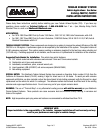
1. Prepare right side manifold prior to installation as
shown in
Fig. 1 and Fig. 2.
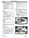
2. Cut the heat riser valve actuating rod with a hack
saw about 5” from the bottom of the vacuum unit.
3. Install vacuum unit and bracket to T.E.S. manifold
on bench. Use nuts, bolts and spacers supplied in
kit
(See Fig. 1).
4. Use extension supplied to connect the two halves of
the actuating rod as shown in
Fig. 2
.
Fig. 1
Assemble heat riser valve vacuum pod and bracket to
manifold (1979 - 1980 Only)
Fig. 2
Cut and extend actuating rod as shown (1979-1980 Only)