


5. Re-connect spark plug wires on lef t side.
6. Re-inst all temperature sensor wire to temperature sensor.
ASSEMBLY - RIGHT SIDE
1.Install T.E.S. flange gasket and one 3/8"-16 x 1" bolt, lock
washer and flat washer at rearmost bolt hole (leave bolt
loose enough to accept T.E.S.).
2.Install dip stick tube and right side T.E.S. manifold from top
side.
3.Inst all remaining bolt s and lock washers. Use original
equipment stud-bolt to re-att ach dip stick bracket.
4. Align all p art s and tighten all right side bolt s at this time.
5. Replace original equipment spark plug ends on cylinders
#4, #6 and #8 with 60 connectors and boots provided in
kit.
6. Re-connect right side sp ark plug wires.
7. Discard O.E.M. heat stove pipe and replace with flexible
tubing supplied (if applicable).
8. To prevent cont act with the hot T.E.S. tubing, use nylon tie
wrap (supplied) to secure the heater hose to the a.c.
dryer.
PLEASE complete and mail your warranty card. Be sure to write the model number (#6661) in the Part #____ sp ace.
THANK YOU.
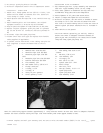
Figure 1
Bend air conditioning support bracket approximately 5 using crescent wrench. Be sure that there is adequate clearance
between the hose’s aluminum tubing and right side inner fender panel af ter support bracket is bent.
CROSSOVER PIPE ASSEMBLY
1. Slip crossover pipe into Y -pipe assembly and extension
tube onto Y -pipe assembly outlet (do not clamp).
2. Place donut gaskets on extensions and slip tube into
muffler inlet. Align p art s and st art flange bolt s.
3. Check alignment of all p art s then secure bolt s.
4.Inst all U-clamp s and tighten all nut s and bolt s.
5. Re-inst all O2 sensor. Use anti-seize on threads of sensor
and torque to 30 f t./lbs. Re-route O2 sensor wire from
wire loom to O2 sensor making sure all wires are clear of
exhaust system (O2 sensor extension wire is included in
kit).
6. Lower vehicle to the ground.
CAUTION: Before operating you vehicle, check to
ensure that there is adequate clearance between all
part s of your TES (including A.I.R. tubes) and all brake
lines, fuel lines, sp ark plug wires, etc.
HARDWARE SUPPLIED
1- Manifold lef t side #25-9057
1- Manifold right side #25-9096
1- Extension pipe right side #25-
9563
1- Extension pipe lef t side #25-9562
1- Muf fler extension #25-9564
4- Flat washers, 3/8"
16- Hex header bolts, 3/8"-16 x 1"
1- Flange connector
1- U-clamp, 2-1/2"
1- U-clamp, 3"
2- Chevy V8 port gaskets
2- Donut gaskets, 2-1/2"
1- Flex tubing, heat stove to air
cleaner
4- Hex bolt, 3/8"-16 x 2"
20- Lock washers, 3/8"
2- Tie wrap s, 10"
1- Bolt 3/8-16 x 1-3/4"
1- S pacer tube 5/8 x .724"
2- Band-clamps
2- Hex nuts, 10-32
2- Hex cap screws, 10-32 x 1"
5- S park plug boots
5- Spark plug boot ends
2-Star washers; 3/16"