


Catalog #66332, #66333
©2006 Edelbrock Corporation
Page 2 of 2
Brochure #63-66332
Rev. 8/06 - DA/mc
• DISASSEMBLY
1. Disconnect negative battery cable.
2. Disconnect and remove both left and right 02 sensors.
3. Unbolt the exhaust hanger/transmission heat shield
assembly from transmission.
4. Disconnect both left and right exhaust pipes from stock
manifolds and allow pipes to hang.
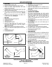
5. With a sawzall, cut left side pipe directly in the middle of the
straight between bends right under bell housing,
(See Fig.
1)
.
6. Cut right side exhaust pipe directly in the middle of the
straight between bends,
(See Fig. 2)
.
• RIGHT SIDE
1. Disconnect and remove spark plug wires.
2. Disconnect E.G.R. flange.
3. Unbolt dipstick tube.
4. Unbolt and remove manifold.
5. Install T.E.S. flange gasket and TES manifold from top.
Install header bolts supplied and leave loose enough to
ensure proper alignment.
NOTE: Use flat washers and lock washers on all bolts.
6. Install E.G.R. flange using supplied gaskets, bolts and lock
washers.
7. Re-install spark plug wires.
8. Re-fasten dipstick tube.
INSTALLATION INSTRUCTIONS
• LEFT SIDE
1. Disconnect and remove spark plug wires.
2. Unbolt and remove manifold.
3. Install T.E.S. flange gasket and T.E.S. manifold from top.
Install header bolts supplied to ensure proper alignment and
tighten bolts.
4. Re-install spark plug wires.
• CROSSOVER PIPE ASSEMBLY
1. With exhaust hanger/transmission heat shield assembly
bolted back on transmission holding the exhaust pipes in
their natural position, install and bolt exhaust pipes to
headers using 3/8" x 16 x 2-1/2" hex bolts, 3/8" flat
washers, 3/8" lockwashers and 3/8" hex nuts. Use the 3"
donut provided in kit.
2. Check alignment of pipes to the catalytic converter, secure
bolts,
(See Fig. 3).
3. With everything in place, tack weld exhaust pipes to
catalytic assembly.
4. Unbolt whole exhaust assembly from vehicle and let it hang.
Complete weld around pipes.
5. Bolt assembly back in vehicle and check for clearance.
6. Re-install 02 sensors. Use anti-seize on threads of sensor.
Route wires clear of exhaust system.
7. Lower vehicle to ground.
• FINAL INSPECTION
1. Check all lines (hydraulic, vacuum, air conditioning and fuel)
to ensure there is adequate clearance to T.E.S. components.
2. Re-connect battery.
3. At this point it is a good idea to look everything over and
make sure that nothing was missed in assembly.
4. Start vehicle and bring up to normal operating temperature.
Check for possible leaks.
5. Turn engine off and let cool. Tighten all bolts again.
• CAUTION: Before operating your vehicle, check to ensure
that there is adequate clearance between all parts of your
TES (including A.I.R. tubes) and all brake lines, fuel lines,
spark plug wires, etc.
6"
Cut Line
Exhaust Hanger
Fig. 1
Left Side Stock Exhaust
Pipe
8"
Cut Line
Exhaust Hanger
Fig. 2
Right Side Stock
Exhaust Pipe
Make Sure There
is Equal Spacing
All The Way Around
Donut Gasket
Fig. 3
Side View of Extension
Pipe Connection
Edelbrock Corporation, 2700 California St., Torrance, CA 90503
Tech Line: 1-800-416-8628
E-Mail: Edelbrock@Edelbrock.com