


©2008 Edelbrock Corporation
Rev. 8/08 - AJ/mc
Catalog #65932 & 65933
Brochure No. 63-65932
Page 2 of 2
ASSEMBLY
1. Install the supplied gasket onto the cylinder head
dowels. Place a small amount of anti-seize on
the threads of each of the eleven (11) factory
intake and exhaust bolts.
2. Install the header onto the cylinder head and
support with loosely installed bolts in locations
3, 6, and 7.
3. Install bolts 1, 2, 4, and 5 about three turns into
engine block. Guide the intake manifold onto the
cylinder head dowels. Loosely install all
remaining intake/exhaust factory bolts. Be sure
the header and intake manifold seats flush as
bolts are tightened.
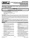
4. Torque all exhaust and intake manifold bolts to
25 ft. lbs. in the sequence shown in
Figure 1.
Insert the supplied conical gasket onto the
headpipe. Re-connect headpipe to the header
with the supplied 3/8” hardware.
5. Re-install the power steering pump and mount
bracket to the intake manifold. Re-install the
belt and adjust the belt tensioner to the vehicle
specification.
6. Re-connect all vacuum and electrical
connections on the intake manifold. Re-install
the throttle cable, transmission pressure line
cable and cruise control (if applicable).
7. Re-install the fuel line. Install and re-connect
the exhaust O2 sensors.
8. Re-install the air inlet hose onto throttle body.
Re-install the air cleaner assembly, if removed.
9. Re-connect the battery. Start the engine and
listen for exhaust leaks. Check the fuel line for
any leaks. Once normal operating temperatures
have been reached, drive the vehicle and listen
for any leaks or rattles. Correct as necessary.
KIT CONTENTS
Qty
. Description
❑ 1 Header assembly (#25-9379)
(
Ceramic-Coated)
❑ 1 Header assembly (#25-9377)
(
Ti-Tech-Coated)
❑ 1 Port Flange Gasket
❑ 2 3/8 Hex Bolts
❑ 2 3/8 Hex Nuts
❑ 2 3/8 Flat Washers
❑ 2 3/8 Lock Washers
❑ 1 Donut Gasket
Edelbrock Corporation, 2700 California Street, Torrance, CA 90503
Toll-Free Tech Line: 1-800-416-8628
Office: 310-781-2222
Tech E-Mail: edelbrock@edelbrock.com
O
2
Sensors
FIGURE 1
2
8
7
11
5
10
1
3
4
9
6