


©2006 Edelbrock Corporation
Brochure #63-0037Page 2 of 3
Catalog #4760, 4761, 4764, 4765, 4767, 4768
Rev. 1/06 - RS/mc
1. Remove old intake and related hardware (Refer to factory service
manual, if needed).
TIP: Remove oil filter (install before starting engine) and intake
support bracket from the underside of car to simplify the removal
of the old intake, remove old intake as an assembly. The intake
support bracket will not be needed on the new intake.
2. Remove old gasket from head and clean head surface. To prevent
gasket pieces from falling into ports when cleaning old gaskets,
stuff paper or rags into ports. When clean, remove stuffing
carefully making sure all particles are removed. Wipe surfaces
clean with rags using lacquer thinner to remove any oil or grease.
NOTE: This is a MUST to ensure proper sealing.
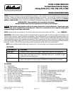
3. Transfer vacuum fittings, hardware, Idle Air solenoid (IAC), and
sensors as applicable and install coolant fittings
(See Fig. 1)
.
INSTALLATION PROCEDURE
BEFORE BEGINNING: If you are installing a manifold with a secondary fuel system (4761, 4765, or 4768), it is recommended to install the
secondary fuel rail and your injectors BEFORE installing the intake manifold onto the engine. See the “Special Instructions for 4761, 4765, and
4768” section on Page 3 for instructions regarding fuel rail installation.
NOTE: To ensure maximum performance and a proper seal, Edelbrock gaskets which are
specifically designed and manufactured for use with Edelbrock parts must be used.
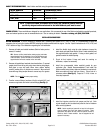
Fig. 2
GASKET RECOMMENDATIONS: Install intake manifolds using the gaskets recommended below.
INTAKE MANIFOLD REFERENCE RECOMMENDED GASKET
4760, 4761 None Edelbrock #15042
4764, 4765 None Edelbrock #15041
4767, 4768 None Edelbrock #15043
POWER OPTIONS: These manifolds are designed for race applications. We recommend the use of the Edelbrock adjustable camshaft sprockets,
cams and exhaust system as seen at www.edelbrock.com. See our catalog for details. To order a catalog, call (800) FUN-TEAM.
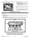
4. Install the throttle body using the stock hardware (remove the
stock studs and install them into the Victor X intake manifold) and
the supplied throttle body gasket. If using a stock gasket, cut
gasket to match the intake opening.
5. Check all fuel injector O-rings and seals for cracking or
brittleness, replace as necessary.
6. Install the recommended intake manifold gasket for your
applicaton
(See “Gasket Recommendations”)
and install the
intake manifold using factory studs and hardware (or equivalent).
Make sure studs are clean and free of burrs. Torque nuts in a
crisscross pattern
(See Fig. 2)
. Torque to 17 ft. lbs. in two- or
three-step sequence.
7. Install fuel injectors, stock fuel rail spacers and fuel rail. Each
injector should be able to rotate freely after the fuel rail holdown
bolts are fully tightened.
NOTE: Certain models and years did not use fuel rail spacers
(such as Integra Type-R and late Integra LS models). These
applicatons may require the use of fuel rail spacers in order to
install the Victor X intake manifold. Use the supplied fuel rail
spacers if necessary.
Fig. 1
1/4” NPT
1/8” NPT
1/4” NPT
1/8” NPT
MAT
Sensor
1/8” NPT
3/8” NPT