


©2006 Edelbrock Corporation
Brochure #63-0037Page 3 of 3
Catalog #4760, 4761, 4764, 4765, 4767, 4768
Rev. 1/06 - RS/mc
SPECIAL INSTRUCTIONS FOR 4761, 4765, AND 4768
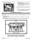
NOTE: Basic manifold installation is the same as manifolds without a fuel rail. Install fuel rail before continuing with the remainder of the
installation. Manifolds are designed to be used with either the Pico style injector or the Bosch style injector. Refer to Figure 4 during the fuel rail
installation process.
Pico-Style Injectors: When using Pico-style injectors, attach fuel rail directly to intake location “A” using the two 1/4-20 x1-1/8” hex-
head screws supplied in kit.
Bosch-Style Injectors: When using Bosch-style injectors, attach bracket “B” to the fuel rail with the supplied 1/4-20 x 3/4” Allen-head
screws. Next, attach the fuel rail to the intake manifold using the two 1/4-20 x 1-1/8” screws and 1/4” lockwashers as shown.
Edelbrock Corporation • 2700 California St. • Torrance, CA 90503
Tech-Line: 1-800-416-8628 • E-Mail: Edelbrock@Edelbrock.com
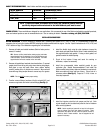
8. When installing fuel pressure regulator, rotate assembly 180
degrees to clear the intake
(See Fig. 3)
.
9. Install fuel and vacuum connection along with all needed sensor
wires as originally equipped.
Special Instructions for #4760/4761: In some cases, the idle
air control motor (IAC) wire harness will no longer reach the
solenoid. Use the supplied wires and connectors supplied in kit
to extend the factory wire harness.
10. Install air inlet
(Some air inlet systems may require modification)
.
11. Check all fluid levels, start engine and check for possible vacuum
leaks.
12. This is a race manifold with different flow characteristics than
your stock manifold, modifications to your fuel curve and cam
timing will be necessary for optimal performance.
Fig. 3
Fuel Rail
Bracket
“B”
Location
“A”
#4761 with Bosch-Style Injectors
3/8” NPT
3/8” NPT
Fig. 4