


Catalog #3881
Rev. 6/06 - RS/mc
©2006 Edelbrock Corporation
Brochure #63-3881
Page 3 of 3
FUEL LINE REMOVAL AND INSTALLATION
(Optional; Do Not remove fuel lines unless necessary)
CAUTION: Fuel system is under pressure. Pressure must be
released before servicing fuel system components.
1. Remove fuel cap to release fuel tank pressure. Using EFI pressure
gauge (T80L-9974-B), release fuel pressure from fuel pressure
relief on fuel rail.
2. Before disconnecting fuel lines, disconnect negative battery cable.
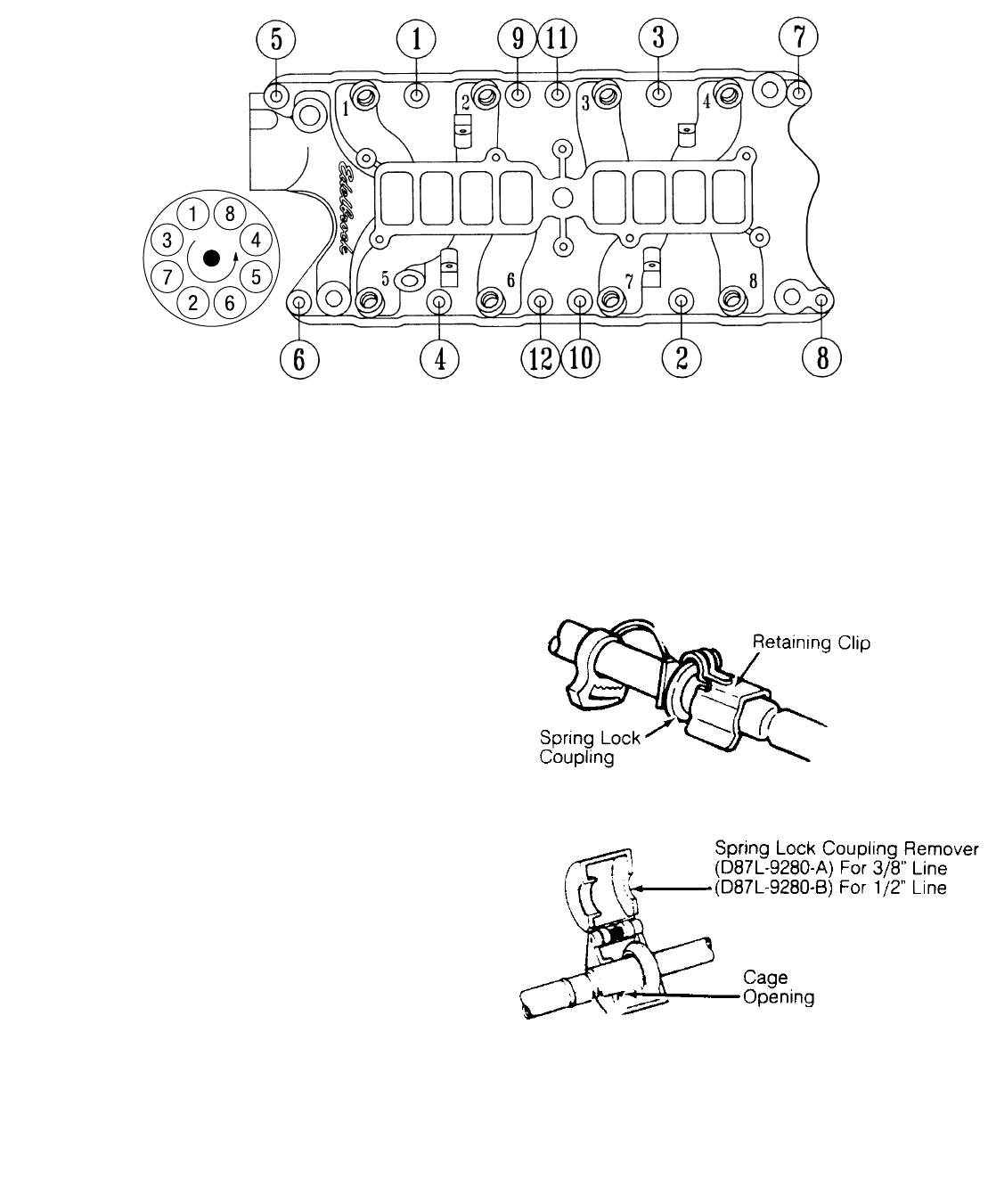
To disconnect fuel lines, remove retaining clip from outside of fuel
line coupling.
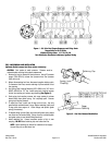
3. Use Spring Lock Coupling Remover (D87L-9280-A) for 3/8" line or
(9D87L-9280-B) for 1/2" line. Install spring lock coupling remover
on fuel line coupling so it enters cage opening
(See Figure 2)
.
4. Push spring lock coupling remover into cage opening to release
female fitting from garter spring. Pull couplings apart. Remove
spring lock coupling remover.
5. To install fuel lines, install new O-rings on fuel lines. Use only
specified fuel resistant brown O-rings. Before installing, lightly coat
O-rings with clean engine oil. Clean fittings and replace garter
spring (if necessary).
6. Fit female fitting to male fitting and push until garter spring snaps
over flared end of female fitting. Ensure lines are locked together
and garter spring is over female fitting flared end.
7. Install retaining clip. Ensure horseshoe portion of clip is over
coupling. DO NOT install retaining clip over rubber fuel line.
NOTE: Black retaining clip should be installed on fuel supply
line and Gray clip on fuel return line.
Figure 1 - 5.8 Liter Ford Torque Sequence and Firing Order
Torque Bolts to 18-20 ft/lbs.
Standard Firing Order: 1-3-7-2-6-5-4-8
Turn Distributor Clockwise to Advance Ignition Timing
Figure 2 - Fuel Line Removal/Installation