


©2006 Edelbrock Corporation
Brochure #63-1602Page 2 of 6
Catalog #1602, 1615
Rev. 4/06 - RS/mc
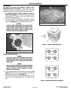
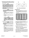
1. Before installing heads on engine, remove valve springs, retainers
and locks from one head. Leave the valve seals on to hold the
valves in position during the clearance check.
2. Use a 6" caliper to measure valve tip height from the valve spring
pocket.
3. Find the cam manufacturer’s "Valve lift at Top Dead Center" specs
and subtract this dimension from the valve tip height you measured
in step 2.
4. Using the calipers to check the new valve tip height, open the valve
by the amount calculated in step 3.
5. Repeat this process for the other valve. Note that intake and
exhaust "Valve lift at Top Dead Center" dimensions are usually
different.
6. With both intake and exhaust valves open to the correct
specifications, use a .060" feeler gauge to check clearance between
the valve heads. If less than .060" clearance exists, you run the risk
of valves hitting during engine operation, voiding any warranty on
these cylinder heads. If there is less than .060" clearance, select
another cam for your engine.
CHECKING VALVE-TO-VALVE CLEARANCE
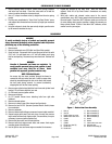
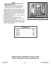
1. Bolt (4)
2. Seal (4)
3. Upper rocker arm cover
4. Middle rocker arm cover
5. Gasket
6. Gasket
7. Gasket
8. Rocker arm shaft (2)
9. Rocker arm
10. Rocker arm
DISASSEMBLY
11. Bolt and washer (2)
12. Bolt and washer (2)
13. Bolt and washer (3)
14. Bolt and washer (3)
15. Gasket
16. Gasket
17. Lower rocker arm cover
18. Umbrella valve
19. Rocker arm bushing (4)
WARNING
To avoid accidental start-up of vehicle and possible personal
injury, disconnect the battery cables (negative cable first) before
performing any of the following procedures.
1. Remove seat.
2. Remove instrument cover (FX/Softail and Dyna Glide models).
3. Drain fuel tank. Disconnect fuel line and plug end of fuel line with
5/16" bolt. For split tanks use a 1/4" bolt and rubber cap to plug
fuel line and opening. Disconnect any wires from tank. Remove fuel
tank.
WARNING
Gasoline is flammable and fumes are explosive. To
avoid possible personal injury, drain gasoline in well
ventilated area away from fire or flame. Drain
gasoline into approved gasoline container only.
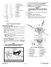
NOTE: FX/Softail Models
An access hole has been provided through the frame to
remove the left rear rocker box bolt. A rolled up paper tube
should be inserted through the hole in the frame and around
the bolt head during removal, to prevent accidentally
dropping the bolt into the frame opening.
4. Remove upper cylinder head stabilizer from frame and cylinder head
bracket. Do not loosen stabilizer jam nuts.
5. On FXR model remove ignition switch.
6. Remove spark plugs.
7. On FLT models remove lower attaching bolts from right side
footboard.
8. Remove exhaust system.
9. Remove air cleaner cover, filter element and back plate.
10. Remove fuel and V.O.E.S. (Vacuum Operated Electric Switch) hoses
from carburetor.
11. Remove carburetor.
12. Remove intake manifold flange screws and remove intake manifold.
13. Support engine with small jack and piece of wood, then remove
large center bolt from front engine mount. On some bikes, it may be
necessary to remove ignition module first.
14. Remove bolt from outer end of front stabilizer.
15. Remove both front engine mount bolts and remove front engine
mounting plate with stabilizers.
16. Use the jack to raise and lower engine as needed for clearance.
Figure 1 - Rocker Arm Cover Assembly.