


©2008 Edelbrock Corporation
Brochure #63-1551Page 6
Edelbrock E-Force Supercharger Kits
Rev. 8/08 - AJ/mc
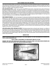
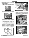
6. For 1986 and earlier applications, install the top plate to intake
manifold bolts and torque bolts to 8-10 ft./lbs. On E-Tec/Vortec
applications, install the top plate to manifold bolts and snug down
with a small box end wrench. You may now install the remaining
four (4) intake manifold bolts (that pass through the top plate) and
tighten all of the manifold bolts to 11 ft./lbs by the sequence shown
in
Figure 11
. Then torque the remaining top plate to manifold bolts
to 8-10 ft./lbs. Tighten bolts in a criss-cross pattern, starting in the
center and working outward.
Figure 11
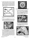
7. Place a clean rag over the carburetor opening in the supercharger to
prevent any debris from entering during the remainder of the
installation.
8. Reinstall the distributor
(See Figure 12)
. Make sure the distributor
is aligned in the same position, with the rotor pointing to the same
terminal as it was when the distributor was removed. You may need
to lift and reinsert the distributor multiple times to align the rotor.
Figure 12
9 Install supercharger drive pulley in front of the factory accessory
crank pulley using the supplied 3/8-24 x 3.75” long shoulder bolts
and 3/8” lock washers
(See Figure 13)
. Install the supplied 7/16-
20 x 2.75” balancer bolt with a 7/16” lock washer first and snug the
bolt down until the pulley is flush. Do not fully tighten at this time.
Slip the drive belt over the top and bottom pulleys, and make sure
the pulleys are in-line. If they are not aligned, remove the drive belt
and pulley from the crankshaft and use the provided shims to align
the pulley. Once properly aligned, torque the balancer bolt to 60
ft./lbs., and torque the pulley bolts to 32-35 ft./lbs. You may leave
the drive belt uninstalled at this time.
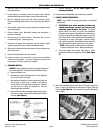
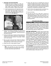
10. Install the supercharger snout support/idler pulley bracket:
A. For standard pulley applications, you will attach the
bracket to the front of the intake manifold using two (2) of
the 3/8-16 x 4” long x 2.75” shoulder bolts
(See Figure
14)
. Install the Alternator Tensioning bracket under the
passenger side bolt
(See Figure 14)
. Align the tensioning
bracket with the alternator and tighten the snout
support/idler pulley bracket bolts. Install the alternator
tensioning bolt, but do not tighten at this time.
Figure 13
Figure 14
Alternator
Bracket
B. Install the idler pulley onto the bracket. Use the remaining
3/8-16 x 4” long x 2.75” shoulder bolt, idler pulley spacer,
and square idler pulley nut to attach the idler pulley to the
bracket
(See Figure 15)
. Make sure the nut is aligned
with the slot on the back of the bracket.
Figure 15
Idler Pulley Nut