


©2004 Edelbrock Corporation
Rev. 6/04 - RS/mc
Catalog # 15022
Brochure # 63-0236
Page 2 of 2
Edelbrock Corporation
2700 California St. • Torrance, CA 90503
Tech Line: (800) 416-8628 • Office: (310) 781-2222
Fax: (310) 972-2730 • E-Mail: Edelbrock@Edelbrock.com
1996-1998 VEHICLES
Tap Into The ECU’s Power Source:
Locate the Ignition Power wire (yellow / black stripe), in
position A-11
(See Fig. 2)
. Cut and strip both ends of the
cut wire. With a splice connector, connect them both to the
red wire on the voltage clamp
(Fig. 3)
.
Tap Into the MAP Sensor Ground Wire:
Find the MAP sensor ground wire (green / white stripe). It is
located at position D-12
(Fig. 2)
. Cut this wire and strip the
cut ends. Use a splice connector to connect both ends of the
cut MAP sensor ground wire to the black wire on the clamp
(Fig. 3)
.
Intercept the MAP Sensor Signal Wire:
Locate the MAP sensor signal wire (red / green stripe)
located at D-3
(Fig. 2).
Cut the wire and strip both ends of
the cut wire. Using a splice connector, attach the blue wire
with a red stripe on the voltage clamp to the end of the MAP
sensor signal wire that leads to the ECU
(Fig. 3)
, and with
the remaining splice connector, attach the blue wire on the
voltage clamp to the other end of the cut wire which leads to
the MAP sensor
(Fig. 3)
.
INSTALLATION (CONTINUATION)
3. Mount the voltage clamp under the dashboard in a
convenient location. Using a heat gun, shrink the insulation
on the splice connectors. Use a piece of heavy cardboard to
shield carpeting and any nearby electrical tape or other
components that could be damaged by heat.
4. Wrap the newly connected wiring with electrical tape to
protect it and secure with tie wraps as necessary.
5. Plug the A & D connectors back into the ECU, and replace the
passenger side kick panel.
6. Reconnect the battery.
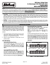
1 2 3 4 5
TPS ECT MAP VCC 1 BKSW
6 7 8 9 10 11 12
KS PO2S/LABEL IAT EGRL VCC 2 SG2 SG1
13 14 15 16
SHO2SG SO2S PTANK EL
1 2 3 4 5 6 7 8 9 10 11
INJ 4 INJ 3 INJ 2 INJ 1 S02SHTC P02SHTC ESOL/E-EGR VTSOL LG 1 PG 1 IGP 1
12 13 14 15 16 17 18 19 20 22 23 24
IACV IACVN IACVP PCS FLR ACC MIL ALTC ICM LG 2 PG 2 IGP 2
25 27 28 29 30
VREF FANC 2WBS VSV SLU
Wire Side Female Terminals
A
32 Pin
D
16 Pin
Figure 2 - 1996-1998 Pin Locations
D-12
D-3
A-11
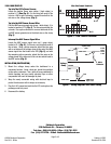
Voltage
Clamp
To Ignition Power
at ECU
To MAP
Sensor
Ground
at ECU
To MAP Sensor
To MAP Sensor
Signal at ECU
Blue/Red
Blue
Black
Red
Splice
Connector
Cut
Figure 3 - Wiring Diagram & Wire Color Coding
Cut
Cut
To MAP Sensor