


©2004 Edelbrock Corporation
Rev. 6/04 - RS/mc
Catalog # 15022
Brochure # 63-0236
Page 1 of 2
MAP Sensor Voltage Clamp
For Turbocharged 1992-1998 Honda Civics
Catalog #15022
INSTALLATION INSTRUCTIONS
®
PLEASE study these instructions carefully before installing your new MAP Sensor Voltage Clamp for turbocharged or supercharged 1992-
1998 Honda Civics. If you have any questions or problems, do not hesitate to contact our Technical Hotline at: 1-800-416-8628, from
7am-5pm, Pacific Standard Time, Monday-Friday, or via e-mail at: Edelbrock@Edelbrock.com. Please fill out and mail your warranty
card. Remember to include the model number of this product in the “Part #____” space. Thank you.
• Description: This MAP Sensor Voltage Clamp limits the voltage sent from the MAP Sensor to the ECU to prevent the ECU from
“seeing” boost pressure in turbocharged or supercharged applications. 1992-1998 Honda Civic ECUs will show an error code for the
MAP sensor if boost pressure is read by the MAP sensor. Limiting the MAP sensor output voltage will keep readings at the ECU from
going beyond the normal range seen on a stock naturally aspirated engine, preventing the MAP error code. This kit includes the
voltage clamp, attached wiring, and the required splice connectors.
• CAUTION: It is highly recommended to use a heat gun to shrink the shrink wrap around the provided connectors after making
connections. Use care when using these devices near any flammable material such as carpeting, sound deadening material, etc.
Keep a Fire Extinguisher rated for use on electrical equipment nearby for added safety.
INSTALLATION PROCEDURE
NOTE: Before beginning, make sure the negative cable on the
battery is disconnected, and that the vehicle is on a level surface
with the wheels blocked to prevent movement of the vehicle
while working in and around the vehicle. It is also helpful to have
a service manual for your particular vehicle on hand for
reference.
1. Remove the passenger side kick panel to gain access to the
factory ECU. (See factory service manual, if necessary).
Unplug the A & D plugs from the factory ECU.
2. Follow the wiring instructions as listed below for your
particular vehicle:
1992-1995 VEHICLES
Tap Into The ECU’s Power Source:
Locate the Ignition Power wire, a yellow wire with a black
stripe, in position A-25
(See Fig. 1)
. Cut and then strip both
ends of the cut wire. With a splice connector, connect both
cut ends to the red wire coming from the voltage clamp
(See
Fig. 3)
.
Tap Into the MAP Sensor Ground Wire:
Find the MAP sensor ground wire. It is a green wire with a
blue stripe. It is located at position D-21
(See Fig. 1)
. Cut
the wire and strip the cut ends. Use a splice connector to
connect both ends of the cut MAP sensor ground wire to the
black wire coming from the voltage clamp
(See Fig. 3)
.
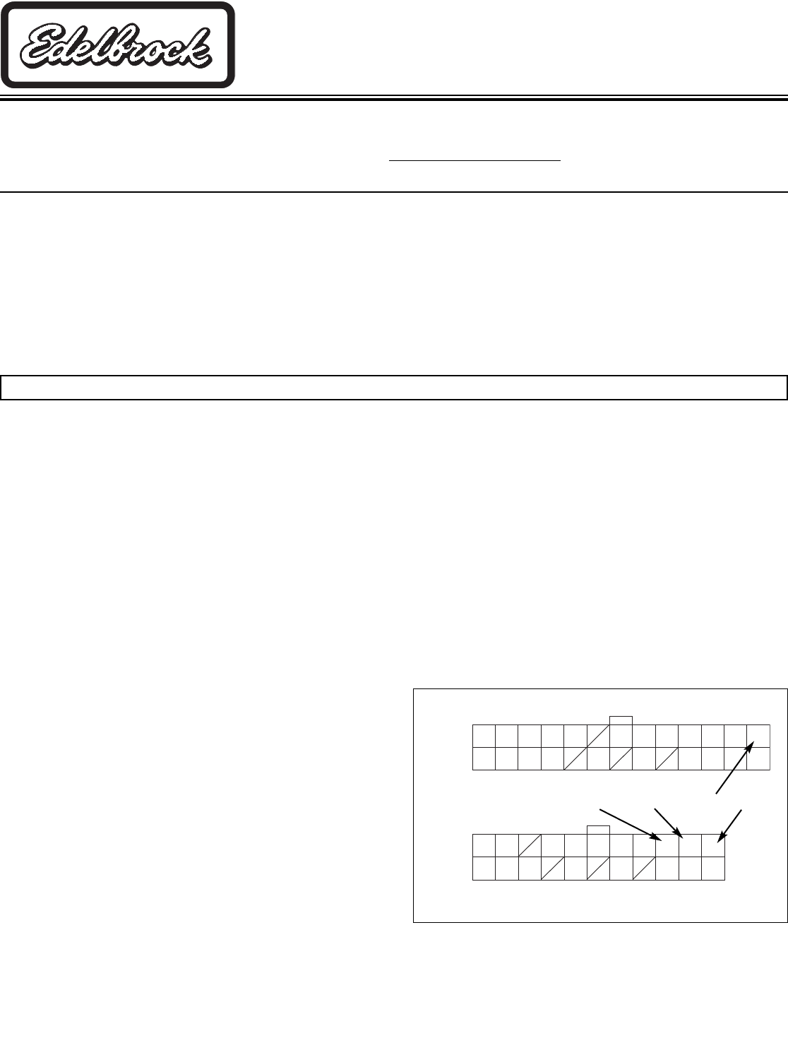
1 3 5 7 9 13 15 17 19 21 23 25
INJ1 INJ2 INJ3 FLR1 EACV WARN ACC ATLSB ATLSA IGP1 PG1 IGP1
2 4 6 8 12 16 20 22 24 26
INJ4 VTS HTCNTL FLR2 FANC ACGC PGS IGP2 PG2 LG1
1 3 7 9 11 13 15 17 19 21
VBU TXD/RXD ACGF TH TW TA PB VCC1 SG1
2 4 6 10 14 18 20 22
BKSW SCS VTM EL O2 SIL/SLU VCC2 SG2
Wire Side Female Terminals
A
26 Pin
D
22 Pin
Figure 1 - 1992-1995 Pin Locations
D-21D-19 A-25
Intercept the MAP Sensor Signal Wire:
Locate the MAP sensor signal wire. This is a yellow wire
with a green stripe located at D-19
(See Fig. 1).
NOTE: On 1994-1995 vehicles, this is a pink wire with a
white stripe, located at position D-17. See Fig. 1 for
reference
.
Cut the wire and strip both ends of the cut wire. Using a
splice connector, attach the blue wire with a red stripe on the
voltage clamp to the end of the MAP sensor signal wire that
leads to the ECU
(See Fig. 3)
, and with the remaining splice
connector, attach the blue wire on the voltage clamp to the
other end of the cut wire which leads to the MAP sensor
(See Fig. 3)
.
D-17
(94-95 MAP Signal)