


Part #1403, 1404, 1405, 1406, 1407, 1409, 1410, 1411, 1412 & 1413
Rev. 6/10 - AJ/mc
Page 3 of 4
©2010 Edelbrock LLC
Brochure #63-0061
6. Do not use more than 6.5 PSI fuel pressure. Excessive fuel
pressure may cause flooding. If your fuel pressure is too high, install
an adjustable pressure regulator, such as Edelbrock #8190.
7. It may be necessary to re-route the fuel line to prevent interference
with the air cleaner. Test fit your air cleaner on your new carburetor
before you begin installation. Look for areas of interference such as
the choke housing, fuel inlet fitting, and fuel line.
PERFORMER SERIES CARBURETOR INSPECTION
1. Check for possible damage to the carburetor.
2. Make sure all throttle linkages operate freely.
3. Ensure that all fuel inlet and vacuum ports are free from packing
material.
CARBURETOR REMOVAL
1. Prior to removal, make sure that the engine is cool.
2. Disconnect the negative battery cable from the battery.
3. Remove air cleaner. Be sure to carefully disconnect any hoses from
the air cleaner and note their location for reinstallation. You may
want to mark them with masking tape for easy reference.
4. Disconnect throttle linkage, kickdown linkage (certain automatic
transmission applications only), cruise control (if equipped) and any
return springs if present.
NOTE: Check carefully for the precise location of all these
linkages and return springs. You may want to mark them with
masking tape for easy reference.
5. Disconnect all wires, tubes, and hoses from carburetor and note
their locations.
NOTE: There should be a maximum of one wire to the electric
choke and one to the idle compensator solenoid (if equipped
with A/C). Any other electrical wiring attached to your
carburetor indicates a computer controlled engine. Edelbrock
carburetors will not function correctly on computer controlled
applications.
6. Disconnect the heater tube from the choke housing (if so equipped).
Edelbrock carburetors do not use the hot-air-style choke, so this
tube may be left disconnected with no problems. If you would like
to cover this opening on a stock manifold, you may be able to use
the appropriate Edelbrock Choke Adapter Plate: #8901 for small-
block Chevrolets; #8961 for big-block Chevrolets; #8951 for
Oldsmobile V8s; #8971 for 351-M/400 Fords; #8981 for 351-W
Fords.
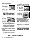
7. Carefully remove the fuel line from the carburetor. TAKE EXTREME
CARE NOT TO SPILL ANY EXCESS FUEL. Place a rag underneath
the fuel line to absorb any spillage that may occur. Certain models
require two wrenches to remove the fuel line; one to hold the fitting
on the carburetor and the second to turn the fitting on the fuel line.
Use a tubing wrench to avoid rounding the tube fitting nut.
8. Remove mounting nuts or bolts and washers. Be sure to put them
where they won’t fall into the intake manifold upon carburetor
removal.
9. Remove carburetor, being careful not to spill any dirt into the intake
manifold. Immediately place a clean rag into the intake manifold to
keep foreign objects out.
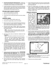
10. Remove old mounting gasket and thoroughly clean mounting
surface. Compare old carb gasket to the gasket included with your
Edelbrock carburetor. If there is a difference in bolt pattern or bore
spacing, an adapter will be required (see “Before Removing Old
Carburetor”, steps #4 & #5).
CARBURETOR PREPARATION
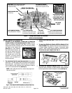
1. Compare the throttle
arm of your new
carburetor with the old
one to be sure that all
required linkages will
hook up. Install the
proper throttle and
transmission linkage
for your particular
application. Throttle
stud is removable and
must be installed in the proper location. Chrysler vehicles with
automatic transmission will require Throttle Lever Kit #1481. Ford
vehicles with automatic transmission and cable linkage will require
Throttle Lever Kit #1483
(See Fig. 6)
and Throttle Cable Plate Kit
#1490 (for 289-302), #1491 (for 351-W), #1493 (for 351-C & 351-
M/400), or #1495 (for 429/460).
2. Check and prepare carburetor for proper vacuum fitting installation
(EGR, power brakes, PCV, distributor, transmission, etc.), using the
supplied vacuum caps, “T” and hose when applicable. If vacuum
port at rear of carb is not used, plug with the 1/4 NPT pipe
plug supplied (Except marine models, port is not drilled).
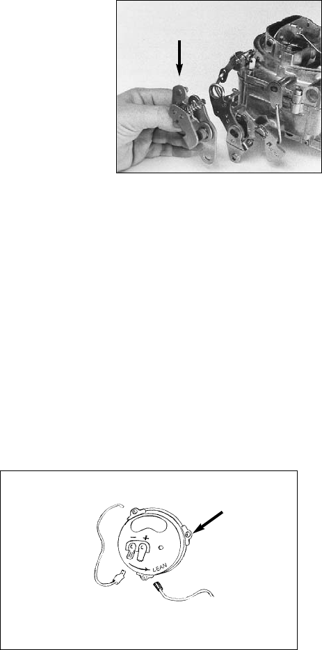
3. On electric choke models
(See Fig. 7)
, remove one choke housing
retaining screw and install eyelet end of choke ground wire (black)
to the choke housing, and reinstall the screw. Connect clip end of
choke ground wire to negative (–) spade terminal on choke housing.
CARBURETOR INSTALLATION
1. Remove rag from intake manifold and install new studs, mounting
gasket and adapters (where applicable).
NOTE: Do not use any cement, glue, or RTV sealant on gasket.
2. Carefully place new carburetor on gasket.
Fig. 6
Ford Throttle Lever #1483
bolts to carb throttle arm
Black wire (–): To Ground
(Carb Body)
Fig. 7
Red Wire (+): To Ignition Key Activated
12V Source (NOT coil or alternator!)
Retaining
Screws (3)