


©2007 Edelbrock Corporation
Brochure #63-0443
Catalog #1400
Rev. 1/07 - RS/mc Page 2 of 5
INSTALLATION PROCEDURE
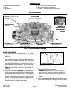
Figure 1 - Fittings and Vacuum Port Locations
CANISTER VAPOR VENT
(#1400 ONLY)
IDLE MIXTURE SCREWS
Left side screw for left side of carb
Right side screw for right side of carb
FUEL INLET for 3/8” hose (Except marine
models #1409 & #1410 which use a 3/8”
inverted flare fitting)
POWER BRAKE PORT
(Except Marine Models)
Rear lower side, 1/4” NPT
MUST BE PLUGGED WITH
1/4” PIPE PLUG (SUPPLIED)
IF NOT USED
IDLE SPEED
SCREW
PCV PORT (For 3/8” hose)
NOT FOR FUEL!
3/16” MANIFOLD VACUUM PORT
(EGR vacuum supply port)
3/16” TIMED VACUUM PORT
(Distributor vacuum advance port for
emissions controlled engines)
PART NUMBER is stamped on
pad at front of carburetor
CARBURETOR PREPARATION
1.
Install proper throttle and transmission linkage for your particular
application. Make sure all linkage is properly secured to carburetor and
works freely.
2.
Check and prepare carburetor for proper vacuum fitting installation
(EGR,
power brakes, PCV, distributor, transmission, etc.) using supplied
vacuum caps, “T”, and hose when applicable. Before removing old
carburetor, determine if distributor vacuum advance port is “timed” (no
vacuum present at idle) or “manifold vacuum” (vacuum present at idle),
and use the matching vacuum port on your Edelbrock carburetor
(See
Figure 1)
. If vacuum port at rear of carb is not used, plug with a 1/4"
pipe plug.
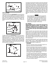
3. For electric choke hook-up
(See Figure 2)
, remove one choke
housing retaining screw and install eyelet end of choke ground wire
(black) to choke housing and reinstall screw. Connect clip end of
choke ground wire to negative (-) spade terminal on choke housing.
Connect red wire spade terminal to positive (+) terminal on choke
housing. Connect other end of red wire to an ignition key activated
12-volt source. DO NOT ATTACH TO COIL OR ALTERNATOR. Ensure
this source maintains 12 volts with engine running.
INSTALLATION OF CARBURETOR
1. Disconnect all linkages and lines from old carburetor, noting their
purpose for reassembly on new carburetor.
CAUTION: When disconnecting fuel line, avoid any exposure to
sparks or open flame. Note position of all throttle and transmission
linkages and/or cables for reassembly. Remove old carburetor and
flange gasket. Do not allow gasket or other material to fall into
manifold.
2. Place new carburetor gasket and adapters (when applicable) on the
manifold. Install carburetor and cross tighten nuts. Be sure not to
overtighten nuts.
Fig. 2
Black Wire (–);
To Ground
(Carb Body)
Red Wire (+); To Key-On 12V
Source
(Not Coil or Alternator!)
Retaining Screws (3)
RECOMMENDED TOOLS
❑ Sockets/wrenches/tubing wrenches
❑ Pliers
❑ Screwdrivers
❑ Hacksaw and/or tubing cutter
❑ #20 Torx Driver (for electric choke models)
❑ Wire crimpers (for electric choke models)
❑ Test Meter or Test Light (for electric choke models)