


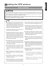
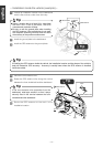
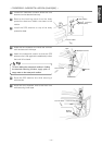

-
12
-
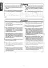
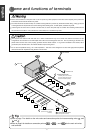
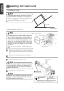
System connection e
System connection e
xample
xample
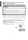
••
Install and connect all of the peripheral units before connecting them to the main unit.
••
Do not remove any of the protective caps (RCA, etc.) unless in use.
••
Be sure to wrap the connection wires with tape (PVC tape) to insulate them.
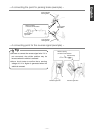
Tip
••
Never cut the insulation on the power wire or use it to power any other main unit. If the rated current
capacity of the power wire is exceeded, fire and electric shocks may result.
••
The wires should be secured with tape or a similar securing method to prevent any obstructions while
driving. If they get wound or entangled around components such as the steering wheel, shifting lever,
or brake pedal, accidents may result.
••
If removing the end of the wire to connect to another wire, be sure to wrap PVC tape or a similar wire
insulating method around the connection to insulate it. If the connection is not insulated, fire or
accidents may result.
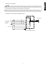
DIN WIRE
(Supplied with CD changer)
Black
TO GROUND
TO BATTERY+12V
(Permanent Supply)
Yellow
POWER CONNECTOR WIRE
(Supplied with CD changer)
REAR
SPEAKERS
TO VEHICLE SPEED PULSE SIGNAL TERMINAL
(Refer to page 10)
Purple/White
TO PARKING BRAKE SIGNAL (Refer to page 11)
Red/White
TO REVERSE SIGNAL (Refer to page 11)
Green
TO BATTERY+12V
(Permanent Supply)
Yellow
TO ACC (Power Supply)
Red
TO HEAD LIGHT SWITCH (Illumination(+))
Orange/White
TO POWER ANTENNA RELAY (Supply)
Blue
TO TURN-ON WIRE OF EACH EQUIPMENT (Supply)
Blue/White
FRONT
SPEAKERS
Black
TO GROUND
INTERCONNECTING WIRES
(Power and front speaker connector)
2
INTERCONNECTING WIRES
(Rear speaker connector)
3
TO MONITOR (remove covers when using external monitor)
TO STEERING REMOTE CONTROL
GPS ANTENNA
9
ANTENNA PLUG
INTERCONNECTING WIRES
(Steering remote control connector)
4
MAIN UNIT
1
BEC105 (sold separately)
NO CONNECTION
CH3083
(sold separately)
13P
4P
8P
1P
10P
6P
13P
2P
Pink
NO CONNECTION
English Español Français Italiano
Nederlands
SvenskaEnglish
Blue/White
20P