


4
Section I – Operating Characteristics
“A” End 9-cylinder, variable delivery axial. . . . . . . . . . . . . . .
piston type pump
“B” End 9-cylinder, fixed displacement axial. . . . . . . . . . . .
piston type motor
Port Connections
(MTR3 & PTR3) AND10050-8 (3/4-16). . . . . . . . . . . . . . . . .
Operating Fluid:
Type Use petroleum oil SAE 20-20W API, MS.. . . . . . . .
Type “A” automatic transmission oil is
also permissible.
Capacity 9/10 quart. . . . . . . . . . . . . . . . . . . . . . . . . . . . . . .
Maximum Displacement 0.645 cu.in per revolution. . . . . . .
Maximum Gauge Pressure 500 psi. . . . . . . . . . . . . . . . . . . .
Input (“A” End Drive) Speed:
Maximum 1800 rpm. . . . . . . . . . . . . . . . . . . . . . . . . . . . . . .
Minimum 1200 rpm. . . . . . . . . . . . . . . . . . . . . . . . . . . . . . . .
Output (“B” End Drive) Speed:
Maximum 1800 rpm. . . . . . . . . . . . . . . . . . . . . . . . . . . . . . .
Minimum 100 rpm. . . . . . . . . . . . . . . . . . . . . . . . . . . . . . . . .
Pump Delivery:
1800 rpm and 500 psi 4.7 gpm. . . . . . . . . . . . . . . . . . . . . .
1200 rpm and 500 psi 3.1 gpm. . . . . . . . . . . . . . . . . . . . . .
Horsepower Ratings:
Maximum input 1.50 @ 1800 rpm. . . . . . . . . . . . . . . . . . .
Maximum output 1.12 @ 1750 rpm. . . . . . . . . . . . . . . . . .
Pump Yoke Control Servo, Handwheel or Lever. . . . . . . . .
Direction of Rotation Optional. . . . . . . . . . . . . . . . . . . . . . . . .
Mounting Position Optional. . . . . . . . . . . . . . . . . . . . . . . . . . .
(see nameplate)
Drive Connections Direct or Indirect. . . . . . . . . . . . . . . . . . . .
Shaft Diameter 0.500 in.. . . . . . . . . . . . . . . . . . . . . . . . . . . . .
Shaft Key 1/8 in. square. . . . . . . . . . . . . . . . . . . . . . . . . . . . .
Section II – Installation
Adjustable speed hydraulic drives are precision built units
and should be treated as such. Careful attention to these
instructions will insure that maximum service life will be
obtained. For installation dimensions, the following drawings
should be referred to:
Model Number
Installation Drawing
TR3 I-259217
MTR3 I-214338
PTR3 I-214337
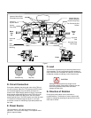
A. Mounting Position
These units can be mounted in any position, provided the
filler cup is above the highest level of the unit (see name-
plates). Also, in the case of the motor units, the drain line
must be connected to the reservoir in such a manner that the
case remains full of fluid.
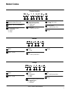
B. Control Position
An optional handwheel or servo control can be mounted on
either side of the variable speed drive or pump. (Model
number codes for the type control and location are shown in
Table 1.) The handwheel control can be moved to the
opposite side of the unit if it is desired.
C. Coupling
Conventional flexible couplings may be used, or these units
may be coupled indirectly through flat or vee belts, chain
drives or gears. If direct coupling is used (see Figure 1), the
shafts must be aligned accurately for maximum service life.
For indirect drive, the pulley, sheave, sprocket, or gear pitch
diameter must be at least 2 inches.
CAUTION
Couplings or pulleys must be assembled to the
shafts by hand. If a pulley or coupling becomes
tight after operation, a wheel puller should be used
to remove it. Pounding will cause damage to the
shaft and bearings. Keys must not be pounded into
the shaft keyways. Material can be removed by
lapping to fit the keys to the shafts.
Two keys are taped to each shaft (see Figure 2). The
stepped section keys are for units replacing -13 design units,
which used #4 Woodruff keys. For new installations, the
square section keys should be used.