


Disassembly/Assembly Instructions - Dynisher
Important: Manufacturer’s warranty is void if tool is disassembled before warranty expires.
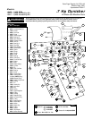
Please refer to parts breakdown for part identification.
Motor Disassembly:
1. Disconnect tool from power source. Remove pneumatic wheel or accessory from spindle.
2. Loosen 01678 Lock Screw and remove handle assembly. Remove flange and spacer from motor shaft.
3. Secure motor housing using padded vise with motor spindle facing upwards.
4. Using an adjustable pin wrench, remove 13432 Spindle Cover.
5. Remove 04014 Set Screw from housing.
6. Pull 13433 Arbor Adapter and planetary carrier assembly from housing.
7. Press planetary carrier assembly from rear 02552 Bearing. Remove ring gear and gears from 53180 Planetary Carrier.
8. Secure planetary carrier in vise and remove 13433 Arbor Adapter. Press carrier from front 02552 Bearing.
9. Grab onto 04017 Rotor/Pinion and pull motor assembly from motor housing.
10. Press 04017 Rotor/Pinion from 13440 Rear Bearing Plate. Press 02649 Rear Bearing from rear bearing plate.
11. Remove 01028 Cylinder and 01185 Rotor Blades from rotor.
12. Press rotor pinion assembly through 01007 Front Bearing and 53183 Front Bearing Plate.
Motor Disassembly Complete.
Housing Disassembly:
1. Position housing in padded vise with air inlet facing up.
2. Remove air fitting by securing 94523 Inlet Adapter with a wrench and twist air fitting from inlet adapter.
Important: 94523 Inlet Adapter must be secured before attempting to remove air fitting to avoid damaging valve body housing.
3. Remove 94523 Inlet Adapter.
4. Remove 95711 Retaining Ring from inlet adapter and separate 94521 Muffler Base from 94522 Muffler Cap. Remove 94528 Felt Muffler.
5. Remove 01565 Air Control Ring from housing.
6. Using a 2.5mm drift pin, tap 01017 Pin from housing and remove throttle lever assembly.
7. Remove 13427 Plug. Pull 13437 Speed Regulator from housing and remove 01024 O-Rings, 07145 Spring, 13439 Ball, and 13435 Valve Stem.
Disassembly Complete.
Motor Assembly:
Important: Be sure parts are clean and in good repair before assembly. Follow all grease, oil, and torque specifications.
1. Place 04017 Rotor in padded vise with threaded spindle facing upwards.
2. Slip 01010 Spacer onto 04017 Rotor.
3. Place a .002" shim into 53183 Front Bearing Plate as an initial spacing and slip 01007 Bearing into plate. Note: 01121 Shim Pack contains .001"
and .002" shims.
4. Press bearing/bearing plate assembly onto rotor.
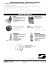
5. Check clearance between rotor and bearing plate by using a .001" feeler gauge. Clearance should be at .001" to .0015". Adjust clearance by repeating
steps 2-4 with different shim if necessary.
6. Once proper rotor gap clearance is achieved, install well lubricated 01185 Blades (4) into rotor slots. Dynabrade recommends using their
95842 Air Lube.
7. Install cylinder over rotor/pinion. Be sure air inlet holes of cylinder face away from 53183 Front Bearing Plate.
8. Press 02649 Rear Bearing into 13440 Rear Bearing Plate. Press bearing/bearing plate assembly onto rotor. Be sure that pin and air inlet holes line up
with pin slot and air inlet holes in cylinder. Important: Fit must be snug between bearing plates and cylinder. If too tight, rotor will not turn freely. Rotor
must then be lightly tapped at press fit end so it will turn freely while still maintaining a snug fit. A loose fit will not achieve the proper preload
of motor bearings.
10. Secure motor housing in padded vise so motor cavity faces upwards. Install motor assembly into housing. Be sure motor inlet is facing the handle and
it drops all the way into housing.
11. Press front 02552 Bearing onto front end of 53180 Planetary Carrier.
12. Apply #271 Loctite
®
to 13433 Arbor Adapter and install onto 53180 Planetary Carrier (torque 17.0 N•m/150 in. - lbs.).
13. Install 53193 Gears, 04026 Bearings and 53182 Gear Shafts onto planetary carrier.
14. Slip 53191 Ring Gear over gears and press rear 02552 Bearing onto planetary carrier.
15. Apply two drops of #271 Loctite
®
to threads of 13432 Spindle Cover.
16. Install 13432 Spindle Cover onto housing to secure motor (torque 28 N•m/250 in. - lbs.).
Motor Assembly Complete.
Housing Assembly:
1. Install 13438 Handle Grip.
2. Insert 13435 Valve Stem through housing and into hole in 13436 Bushing.
3. Insert 13439 Ball, 07145 Spring, 13437 Speed Regulator with 01024 O-Ring in place.
4. Install 13428 Packing onto 13427 Regulator Plug. Secure plug in place torque 8.5 N•m/75 in. - lbs.
5. Insert 94528 Muffler into 94522 Muffler Cap. Install 94521 Muffler Base onto muffler cap.
6. Install 94538 O-Ring into groove on muffler base. Place 95375 O-Ring and 94526 Spacer into recessed area of muffler cap.
(continued on next page)
3