


4
3. Cover the shaft extension with a waxy rust
preventative compound that will keep oxygen away from
the bare metal. (Non-Rust X-110 By Daubert Chemical
Co.)
4. The instruction manuals and lubrication tags are
paper and must be kept dry. Either remove these
documents and store them inside or cover the unit with a
durable waterproof cover which can keep moisture away.
5. Protect reducer from dust moisture, and other
contaminants by storing the unit in a dry area.
6. In damp environments, the reducer should be packed
inside a moisture-proof container or an envelope of
polyethylene containing a desiccant material. If the
reducer is to be stored outdoors, cover the entire exterior
with a rust preventative.
When placing the reducer into service:
1. Assemble the vent plug into the proper hole.
2. Clean the shaft extensions with petroleum solvents.
3. Fill the unit to the proper oil level using a
recommended lubricant. The VCI oil will not affect the new
lubricant.
4. Follow the installation instructions provided in this
manual
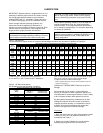
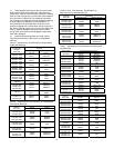
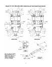
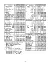
Table 3 – Quantities of VCI #105 Oil
Size Quarts or Liters
TXT / HXT 3A – 305A .1
TXT / HXT 4A – 405A .2
TXT / HXT 5B – 505A .3
TXT / HXT6 – TXT605 .4
TXT / HXT7 – TXT705 .5
VCI #105 & #10 are interchangeable.
VCI #105 is more readily available.
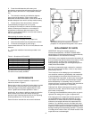
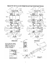
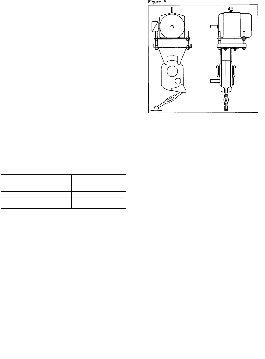
MOTOR MOUNTS
The motor mount must be installed on output end of
reducer as shown in Figure 5.
Remove two or three (as required) housing bolts on output
end of reducer. Place the motor mount in position and
install the longer housing bolts supplied with the motor
mount. Tighten bolts to torque specified in Table 4.
Install motor, drive sheave, and driven sheave so that the
driven sheave is as close to the reducer housing as
practical. Install V-belt and tension with the four adjusting
screws provided on the T-A M motor mount.
Check all bolts to see that they are securely tightened.
WARNING: Belt guard removed for illustration
purposes. Do not operate if belt guard is not in place.
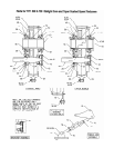
REPLACEMENT OF PARTS
IMPORTANT: Using tools normally found in a
maintenance department, a DODGE TORQUE-ARM
speed reducer can be disassembled and reassembled by
careful attention to the instructions following.
Cleanliness is very important to prevent the introduction of
dirt into the bearings and other parts of the reducer. A tank
of clean solvent, an arbor press, and equipment for
heating bearings and gears (for shrinking these parts on
shafts) should be available.
Our factory is prepared to repair reducers for customers
who do not have proper facilities or who, for any reason,
desire factory service.
The oil seals are of the rubbing type and considerable
care should be used during disassembly and reassembly
to avoid damage to the surface which the seals rub on.
The keyseat in the input shaft, as well as any sharp edges
on the output hub should be covered with tape or paper
before disassembly or reassembly. Also, be careful to
remove any burrs or nicks on surfaces of the input shaft or
output hub before disassembly or reassembly.
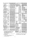
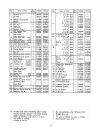
Ordering Parts: When ordering parts for reducer, specify
reducer size number, reducer serial number, part name,
part number, and quantity.
It is strongly recommended that, when a pinion or gear is
replaced, the mating pinion or gear is replaced also.
If the large gear on the output hub must be replaced, it is
recommended that an output hub assembly of a gear
assembled on a hub be ordered to secure undamaged
surfaces on the output hub where the output seals rub.
However, if it is desired to use the old output hub, press
the gear and bearing off and examine the rubbing surface
under the oil seal carefully for possible scratching or other
damage resulting from the pressing operation. To prevent
oil leakage at the shaft oil seals, the smooth surface of the
output hub must not be damaged.