


Section 2 - Taper-Lock Hub Installation
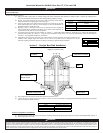
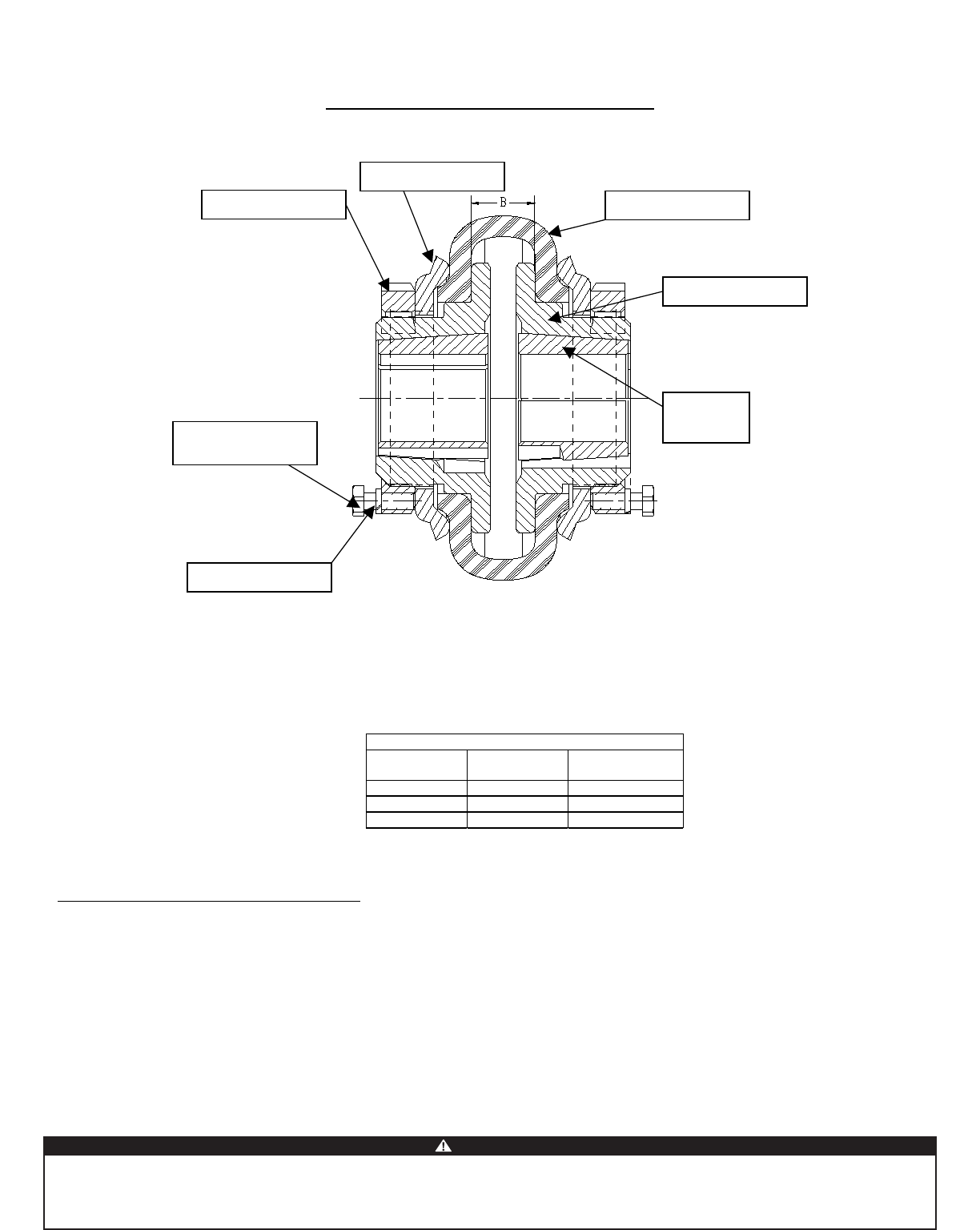
Figure 2: PXGTL Assembly
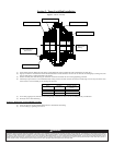
(1) Insert bushing into hub. Match the hole pattern, not threaded holes (each complete hole will be threaded on one side only).
(2) Lightly oil setscrews and thread into those half-threaded holes with the threads in the hub. Do not lubricate the bushing taper, bushing bore, hub
taper or shaft. Doing so could be harmful to the product.
(3) Position assembly onto shaft allowing for mild axial movement of hub that will occur during tightening procedure.
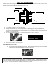
(4) Alternately torque setscrews to recommended torque setting as shown in Table 4 below. Be careful to avoid using worn hex key wrenches as they
tend to result in a loose assembly or may damage the setscrews.
Table 4
Series Bushing Wrench Torque
(in-lb)
50 1215 175
60 2012 280
80 2517 430
(5) To increase gripping force, hammer face of bushing using a brass drift or sleeve. Do not hit bushing directly with hammer.
(6) Re-torque screws after hammering.
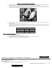
Section 2a – Dismounting Taperlock Bushing Assembly
(1) Remove all setscrews.
(2) Insert one setscrew into any half-threaded hole that is threaded on the bushing.
(3) Loosen bushing by tightening the setscrew.
Hex-Head Micro-
Mount Screw
Lockwasher
Locknut
External Clamp Ring
Hub
Elastomeric Element
Taper-Lock
Bushing
Because of the possible Danger to persons or property from accidents which may result from the improper use of products, it is important that correct procedures be followed: Products must be used in
accordance with the engineering information specified in the catalog. Proper installation, maintenance and operational procedures must be observed. The instructions in the instruction manual must be
followed. Inspections should be made as necessary to assure safe operation under prevailing conditions. Proper guards and other suitable safety devices or procedures as may be desirable or as may
installed, adjusted and maintained by qualified personnel who are familiar with the construction and operation of all equipment in the system and the potential hazards involved. When risk to persons or
property may be involved, a holding device must be an integral part of the driven equipment beyond the speed reducer and output shaft.
WARNING
Baldor Electric Company
. This unit and its associated equipment must be be specified in safety codes should be provided, and are neither provided by nor are the responsibility of
Baldor Electric Company