


Section 3 - Grip-Tight Hub Installation
The DODGE Grip-Tight adapter mounted Para-Flex coupling incorporates a unique way of mounting and dismounting a coupling to and from the shaft. The patented
feature pushes the coupling hub onto the tapered adapter sleeve and locks it into place as the locknut is given a predetermined clockwise rotation. The locknut pushes
against the coupling hub face ensuring a positive uniform engagement of the coupling hub and adapter. Dismounting is accomplished by rotating the locknut in a
counter-clockwise direction pulling the coupling from the adapter and releasing it from the shaft.
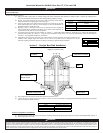
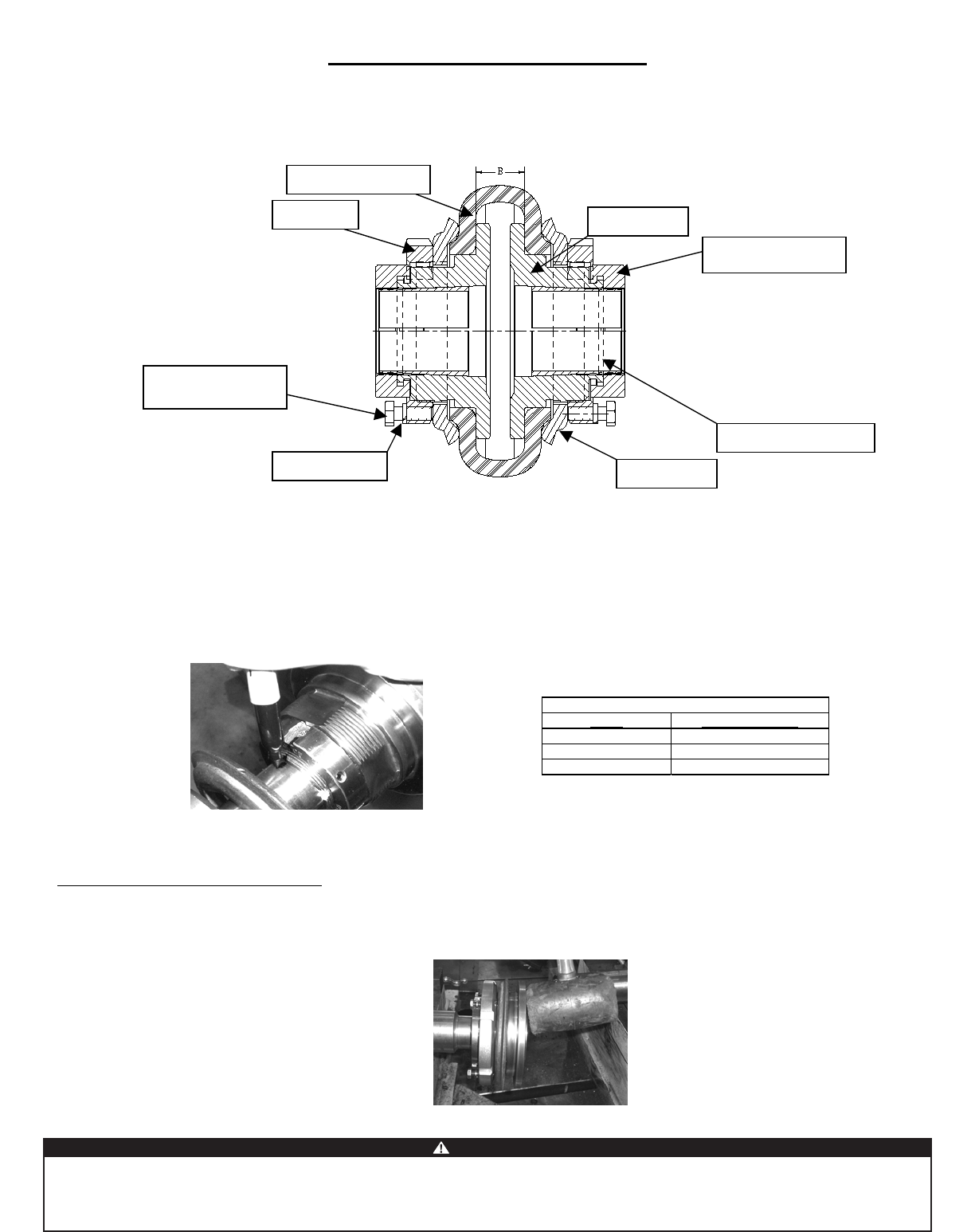
Figure 3: PXGT Assembly
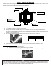
(1) Place the locknut into the groove on the coupling hub, THEN insert the adapter sleeve into the coupling hub in the direction of the taper. Rotate the locknut
clockwise to engage the adapter sleeve.
(2) Do not use lubricants on the shaft or any surfaces of the coupling assembly.
(3) Slide the hub assembly into position onto the shaft. If the unit will not slip onto the shaft, turn locknut counter-clockwise to expand adapter sleeve.
(4) Wearing gloves, rotate locknut clockwise, by hand, as tight as possible until the adapter sleeve grips and does not spin on the shaft. If needed, tap on the
locknut outer diameter while turning locknut to assist with this step. At this point you should not be able to rotate the locknut by hand and you should not be
able to move the hub assembly axially along the shaft by hand. If the hub assembly can be moved axially along the shaft then continue tightening the locknut
until assembly is unable to move axially by hand.
(5)
(6) Lock hub assembly to shaft by rotating locknut, with a spanner wrench or brass drift and hammer, clockwise by amount shown in Table 5.
(7) Tighten locknut setscrew until 3/32” Allen key bends (25 in-lbs).
Section 3a – Dismounting GT Adapter Assembly
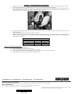
(1) Completely remove the setscrew in the adapter locknut.
(2) Rotate the locknut counter-clockwise with a spanner wrench or brass drift pin and hammer.
(3) The locknut will alternate between spinning easily and becoming snug. When the locknut becomes snug strike, while rotating counter-clockwise,
the backside of the flange with a soft mallet around the entire face as shown to reduce resistance.
(4) Repeat steps 2 and 3 until flange assembly becomes loose.
Table 5
Series Locknut Rotation
50 2/3 Turn
60 1 Turn
80 1 Turn
Clamp Ring
Coupling Hub
Elastomeric Element
Hex-Head Micro-
Mount Screw
Tapered Adaptor Sleeve
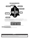
Grip Tight Locknut
Locknu
t
Lockwashe
r
Scribe a line on the locknut above the adapter sleeve slot. This scribe line will be used in step 5 to verify proper locknut rotation.
Because of the possible Danger to persons or property from accidents which may result from the improper use of products, it is important that correct procedures be followed: Products must be used in
accordance with the engineering information specified in the catalog. Proper installation, maintenance and operational procedures must be observed. The instructions in the instruction manual must be
followed. Inspections should be made as necessary to assure safe operation under prevailing conditions. Proper guards and other suitable safety devices or procedures as may be desirable or as may
installed, adjusted and maintained by qualified personnel who are familiar with the construction and operation of all equipment in the system and the potential hazards involved. When risk to persons or
property may be involved, a holding device must be an integral part of the driven equipment beyond the speed reducer and output shaft.
WARNING
Baldor Electric Company
. This unit and its associated equipment must be be specified in safety codes should be provided, and are neither provided by nor are the responsibility of
Baldor Electric Company