


3
v5.3 25523
©
2005 Directed Electronics, Inc.
I. Watch that the LED light remains on as the vehicle is running and turns off when
you rev the engine RPMs to twice the idle rate. The LED light must go out when
you rev the engine to about twice the idle rate to confirm correct tach learning.
J. Turn the key to the “Lock/Off” position.
K. Turn the ON/OFF control switch off and the red LED light will go out. You are
now finished.
Note: Once these steps are complete – you cannot use the LED to confirm tach again.
You can however repeat the above steps to learn tach over again at any time.
OPTIONAL STEPS
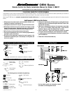
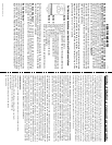
13. Yellow Wire – Headlights/Parking Lights – Control Harness
Connection of the YELLOW wire allows you to activate the low beam headlights
or parking lights for remote start and lock status. After the remote starter has
started the car, the lights will remain on until the remote starter shuts off after 10
minutes, or when the brake pedal is pushed, or when the car is put into gear.
This is
a relay +12 Volts output. Connect the
YELLOW wire to the wire that has power
when the lights are on.
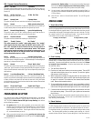
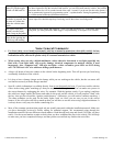
14. Blue – Horn/Siren – Control Harness
The BLUE wire signals the
horn to honk (or siren to
chirp) once each time the
remote starter starts the
vehicle. Connect the blue
wire to the factory horn wire
which is often found
running down the steering column. It will normally show +12 Volts at rest and the
voltage will disappear when the horn is honked. This is a 400 mA transistor
ground output which MUST drive a relay if using a siren or positively
triggered horn.
15. Brown/White – Alarm Disable – Control Harness
The BROWN/WHITE wire is Alarm Disable, which will give out a quick negative pulse
just before starting the vehicle. This wire can be used to turn off the factory alarm
system in vehicles which have them. In most vehicles, this wire is located
in the driver’s kick panel.
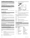
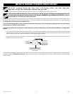
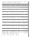
16. White/Black Wire – Ignition #3 – Control Harness
The WHITE/BLACK
wire, is a ground
output that acts just like the Ignition
1 or Ignition 2 relay outputs (active
in the “run” and “crank” positions).
This wire is a 400 mA negative
transistor output and MUST be
set up to power a relay
(not
included). It can be used to power the third ignition wire at the key (necessary for
most Ford vehicles).
This is the wire that can also be used to bypass a passive vehicle anti-theft system by
hooking it up to the Universal Bypass Module. See the Factory Anti-Theft System
section at the end of these instructions.
17. Brown Wire – Accessory Pulse – Control Harness
The BROWN
wire is the Accessory Pulse output which gives out a momentary transistor
ground output 10 seconds after the vehicle is remotely started. This is important in
some vehicles to control the defroster or to control the GM R.A.P. system. Again,
this is a 400 mA transistor ground output which MUST drive a relay (not
included).
Note: If the Ignition 1 and Ignition 2 wires come on whenever the brake is depressed
and the hood is open this just means you need to initialize the unit in section 11.
11. Initializing the Remote Starter
BEFORE THE UNIT WILL DO ANYTHING FOR THE FIRST TIME, YOU MUST INITIALIZE
THE REMOTE STARTER
A. Insert the 30 amp fuse into the fuse holder on the large PINK wire.
B. Turn the control switch on.
C. The remote starter requires the installer to open the hood and then press and
hold the brake pedal. Note: The ignition/dash lights will come on if the unit is
not initialized.
D. While depressing the brake (with the engine off and the hood open) turn the
ignition key to the “RUN” (not “start”) position.
E. Put the car in “DRIVE” from the “PARK” position.
F. Put the car back in “PARK” and release the brake.
G. Turn the key off and remove the key.
Note:
Confirm initialization by turning the ON/OFF control switch “OFF” and then
“ON”. The red LED light on the remote start module will flash once immediately as
the switch is flipped from the “OFF” to the “ON” position.
If the red LED light did not flash when the control switch was turned “ON” REPEAT
STEPS A THROUGH G. See the colored Trouble Shooting Sheets if necessary.
12A. Green Wire – Tach Input – Control Harness
The remote starter has two ways of monitoring the car during the starting process.
Both ways will ensure a clean, accurate start. Read about both methods before
deciding which one to use. Normally you should try the “No Tach
™
”
method first.
“No Tach
™
” Starting
This starting method does not require the connection of the GREEN tach wire. This
method will start the car by reading the car’s voltage before attempting to start, and
then looking for a voltage increase when the alternator kicks in. This feature
automatically takes into account voltage, temperature, and the time since the vehicle
was last run. The “No-Tach
™
””
””
”
starting is preset at the factory and you can skip step
12B if you would like to use it. Note that if the vehicle is hard to start, set Option #3
(section 23) for “extended crank.”
Tachometer sensing
If the vehicle is generally hard to start (i.e. requiring a cranking time of more than 1
second) you will get more accurate starting with the tachometer sensing starting
method. This method starts the car by reading the engine speed (tach) information
from a wire under the hood. If you choose tachometer sensing, connect the GREEN
(18 awg) wire to the car’s tach wire under the hood (normally the negative side of the
coil or tach output of coil pack). After you have connected the GREEN wire, you need
to teach the remote starter the vehicle’s tach rate at idle. Proceed to step 12B.
Note:
You must have already initialized the remote starter from Step 11.
12B. Tach Rate Learning
Note:
Only use if the tachometer sensing method is chosen.
A. Connect the GREEN wire to the car’s tach wire under the hood.
B. Turn the On/Off control switch to the “OFF” position. Wait 5 seconds for the red
LED light flashes to stop.
C. Program the unit to the tach mode by pushing the White “option” button once
and watching the red LED light flash. Now push the start button on the transmitter
for a second until you see the red LED light flash again. You are now in TACH
mode. (If the red LED light flashed twice or sometimes three times – simply push
the transmitter button again until you get only one flash).
D. Wait 5 seconds for the red LED light to flash 3 times.
E. Turn the On/Off control switch back to the “ON” position
F. Start the car with the key and let it get to a
normal
idle. Do not press on the gas
pedal.
G. Push the red “code learn” button for a second.
H. Watch the red LED light. It will come on after 3 or 4 seconds, indicating that the
tach idle rate has been learned.
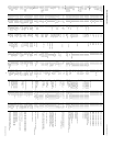
Positive Horn/Siren Relay
Ignition 3
To LARGE 12 Volt
Constant Wire
(Found in Ignition
Switch Wire
Harness)
To Additional
Ignition Wire
(in vehicle)
87
86
White/Black Wire
From
Remote Starter
85
30
87A