


2
© 2011 Directed Electronics. All rights reserved.
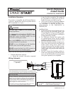
3. Install the VSM200/250 or DSM200/250 using
the information in the wiring diagram and steps
(Note CAUTIONS during installation).
a. Complete the main power connections.
b. Connect the 4-pin extension cable to the
SmartStart module cable.
c. Connect the interface cable to the extension
cable and the other appropriate end into the
Bitwriter port of the Directed system.
d. When power is connected, the module be-
gins an initialization procedure that may
take several minutes. During this procedure,
progress is reported via the flashing Amber/
Green LEDs next to the module cable. When
both LEDs turn on solid, the initialization pro-
cedure is completed (See Status LEDs for a
description of the various LED states).
Note: If the system does not include a remote control,
skip step 4 and proceed to step 5.
4. Re-verify security/remote start system operation:
Perform all basic operations such as Lock, Unlock,
Panic and Remote Start, (Trunk release where ap-
plicable) using the supplied remote control. If the
system operates as expected proceed to the next
step (5). If the system does not operate as ex-
pected, rectify the problem first.
5. Verify and Activate the SmartStart module:
The following steps need to be performed for the
Verification/Activation of the Directed SmartStart
module.
a. Collect Customer Information:
Customer's Full Name:
Customer's E-mail Address:
Customer's mobile phone # and phone carrier
Record/place Module ID # here:
New Account:
Existing Account:
If this is an existing account, are you:
adding a new system:
or replacing an existing one:
b. Log on to: www.directechs.com, and click on
the SmartStart link.
c. Follow the on-screen directions to activate
and test a SmartStart device. If this is the cus-
tomer's first SmartStart system, you will be
prompted to enter their information as col-
lected in step 5a.
d. Test the SmartStart system from the website
using the supplied function links.
e. The customer is sent log-in information for
the new Customer Service Portal via e-mail.
From there, they must provide the required
information. Once completed, the installed
system and account are activated. The cus-
tomer can then open the phone app and be-
gin using the service.
Status LEDs
Amber LED states:
• Off: No cellular communication. Check
connections such as module harness.
• Flashing slowly: The module is seeking
cellular system communication.
If no cell coverage is available the Amber
LED continues to flash slowly, move the
vehicle to a location with better reception.
• Flashing quickly: The module is negotiat-
ing with a cellular system.
• On solid: Communication successfully es-
tablished.
Green LED states:
• Off: Communication not established with
the remote start main unit.
Check connection at the Bitwriter port,
once connected properly the LED turns
on.
• Flashing: Active communication in prog-
ress between the SmartStart module and
Remote Start main unit.
• On solid: Communication successfully es-
tablished with the remote start main unit.
Please return this guide and point the customer to
step 5e after successfully completing the installation
as it contains details required for account setup.
Notes: SmartStart response time can vary depend-
ing on cellular coverage and network congestion.
Operating temperature range: -30°C to + 70°C.
Additional information
can be found at:
www.directechs.com
Logo, Directed Electronics w-driven.eps
Logo, Directed with designed in USA.eps
Logo, Directed with Distributed By.eps
Directed Logo Usage