


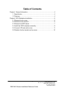
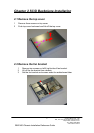
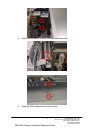

2.5 Connect LED and switch wires
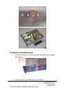
There is one 2 x 9 pin connector on left-bottom side on SC SI backplane. This
connector provides several LED and switch connections for devices. The detail
pin definition is listed below.
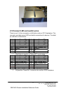
Pin 1 Device 1 Power LED - Pin 2 Device 1 Power LED +
Pin 3 Device 1 Access LED + Pin 4 Device 1 Access LED -
Pin 5 Device 2 Power LED - Pin 6 Device 2 Power LED +
Pin 7 Device 2 Access LED + Pin 8 Device 2 Access LED -
Pin 9 Device 3 Power LED - Pin 10 Device 3 Power LED +
Pin 11 Device 3 Access LED + Pin 12 Device 3 Access LED -
Pin 13 Fail LED - Pin 14 Fail LED +
Pin 15 N/A Pin 16 N/A
Pin 17 Reset - Pin 18 Reset +
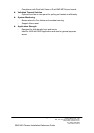
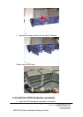
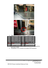
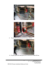
1. Check the pin number of “Reset SW” on connector.
Pin 1 Device 1 Power LED - Pin 2 Device 1 Power LED +
Pin 3 Device 1 Access LED + Pin 4 Device 1 Access LED -
Pin 5 Device 2 Power LED - Pin 6 Device 2 Power LED +
Pin 7 Device 2 Access LED + Pin 8 Device 2 Access LED -
Pin 9 Device 3 Power LED - Pin 10 Device 3 Power LED +
Pin 11 Device 3 Access LED + Pin 12 Device 3 Access LED -
Pin 13 Fail LED - Pin 14 Fail LED +
Pin 15 N/A Pin 16 N/A
Pin 17 Reset - Pin 18 Reset +
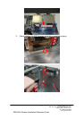
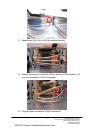
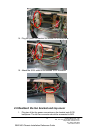
2. Plug “Reset SW” connector into pin 17 & 18 on connector.
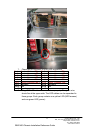
3. Plug another “Reset SW” connector into another SCSI backplane.
Chenbro Micom CO., LTD.
15Fl., No. 150, Jian Yi Road, Chung Ho City,
Taipei Hsien, Taiwan, R.O.C.
Tel: +886-2-8226-5500
www.chenbro.com.tw
11
RM21400 Chassis Installation Reference Guide