10
Tongue and Ramp Assembly Instructions
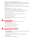
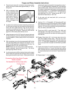
1. Place the main frame (#1) on blocks or some other sturdy
support so that the frame rests approximately 8" - 10" off
the ground.
2. With an assistant, place
tongue assembly (#2)
into main frame channel
and position latch on
tongue approximately 3”
from front of channel.
Clamp tongue to main
frame and support front
of tongue.
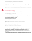
3. Locate the four bullet connectors extending out the back
of the tongue and plug into the connector protruding from
under the main frame channel. Plug into the flat four
connector by matching the colors. Do not cross colors
when making this connection. Make sure that the two
pigtails for the license plate bracket are out.
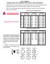
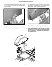
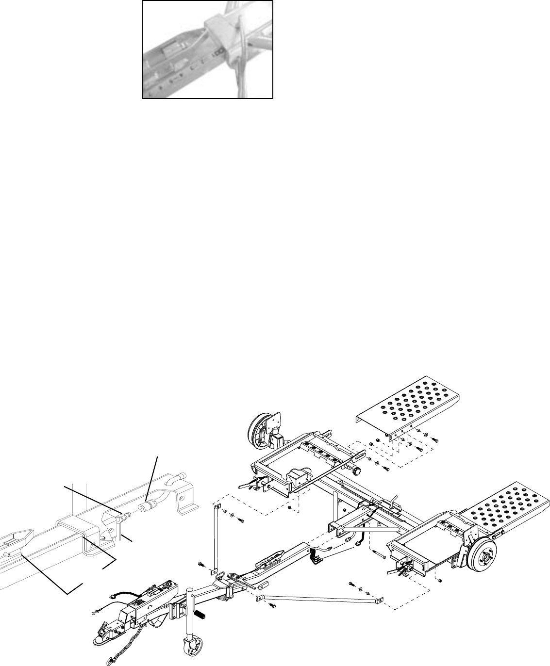
4. Using the open end of a 9/16” wrench to support the back
of the male coupler, (as shown below) push drip free quick
couplers together. (Factory setup units will not havequick
couplers)
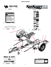
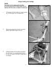
5. With an assistant, mount the tongue assembly (#2) to the
front of the Kar Kaddy main frame and use a 5/8" x 4-1/2"
grade 5 bolt (#3) and lock nut (#4)(torque to 50 ft. lbs). Do
not torque over 50 ft. lbs. or bed will not tilt.
NOTE: Brake line and wiring must be above bolt also
coupler assembly must be ahead of bolt. Do this by
opening tongue about half way.
6. Lay the bracing struts (#5) out along the tow dolly tongue
with the back end (the end with the larger hole in it) of the
bracing strut toward the main frame. Loosely bolt the back
of each bracing strut to the trailer frame as shown using 1/
2" x 1-1/2" grade 5 bolt (#6), flatwasher (#7), pivot bushing
(#8) and locknut (#9). Hold up the front end (the end with
the smaller hole) of each bracing strut to the tongue and
secure with two 5/8" x 1-1/4" epoxied hex head bolts (#10)
and nut plate (#14). Torque the 1/2" x 1-1/2" bolt with the
pivot bushing to 75 ft. lbs. Torque the two 5/8" x 1-1/4"
epoxied hex head bolts to 100 ft. lbs.
7. On the main unit, pull ramp latch (#11) out and up in
unlatched position.
8. Use four 1/2” x 1-1/2” bolts (#6), 1/2” flat washers (#7) and
yellow plated bushings (#12) and place in the front slotted
hole and the rear slotted hole on both sides of ramp (#13).
Use four 1/2” nylon lock nuts (#9) and snug these bolts so
they can slide up and down in slot.
9. Place ramp (#13) in main frame (#1). Front bolts and
bushings go in front open slot of ramp mount. Lift ramp
up and push forward until rear bolts and bushings go into
rear half slot.
10. Engage Ramp latch (#11) and move ramp around so
latch can engage through ramp. With the use of two
clamps, secure ramp to main frame. Install the remaining
1/2” x 1-1/2” bolts (#6), flatwashers (#7), yellow bushings
(#12), and nylon lock nuts (#9) into the remaining slotted
holes.
11. Tighten all six bolts. Pull and lift ramp latch (#11) and pull
ramp back and fold up. If ramp is too tight when pulling
back, reclamp ramp as in previous step and loosen bolts
so ramp lowers away from main frame. Tighten bolts and
retry.
12. Repeat steps 7-11 for other side.
Connector
1
2
3
4
5
5
6
7
8
9
9
67
8
10
10
6
6
6
7
7
7
9
11
12
12
13
Female Coupler
Connecting Drip Free Quick Coupler
brake couplers.
Not needed for factory setup units.
Male Coupler
9/16 Wrench
3”
14


