


Page 18
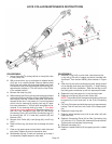
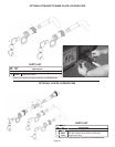
LOCK COLLAR MAINTENANCE INSTRUCTIONS
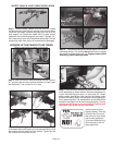
DISASSEMBLY:
1. Leave Aluminator
®
on towing vehicle or clamp hitch tube
in heavy-duty vise.
2. With a screw driver, pry up on bottom of release handle
(#13) ear to to remove handle. Remove bellows boot
(#14) from lock collar (#6) and slide bellow boot back.
Pull back the Lock Collar (#6) and push the Rear Leg (#7)
approximately halfway in. This will hold the Lock Collar
in the release position.
3. Remove the snap-ring (#8).
4. While holding Lock Collar, pull rear connecting leg outward
to the latch position and collar will then slide off outer tube
and hang on rear leg. Inside of lock collar (#6) can be
cleaned at this time. Lock pawls (#11) can be removed
at this time for cleaning by pushing rear leg (#7) back
into outer tube about 1”, this will push lock pawls out for
removal. If not removing shaft go to step 7. For shaft
removal or o-ring replacement; Remove caplugs (#1)
from the Front Connecting Leg Tube (#2) and unbolt
Connecting Clevis (#3) from Rear Connecting Leg (#7)
by removing the 1/2” x 3” bolts (#4), washers (#5) and
locknuts (#12).
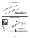
5. Remove Lock Collar (#6), Lock Spring (#9), and O-ring
(#10).
6. Slide out Rear Leg, be careful not to damage the shaft
seal.
7. Clean o-ring groove area and oval hole in outer tube and
lock pawls. Inspect all parts for excessive wear.
8. Reassemble this leg, If shaft not removed, go to step 3
of reassembly. Repeat steps for other side.
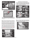
REASSEMBLY:
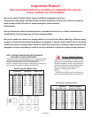
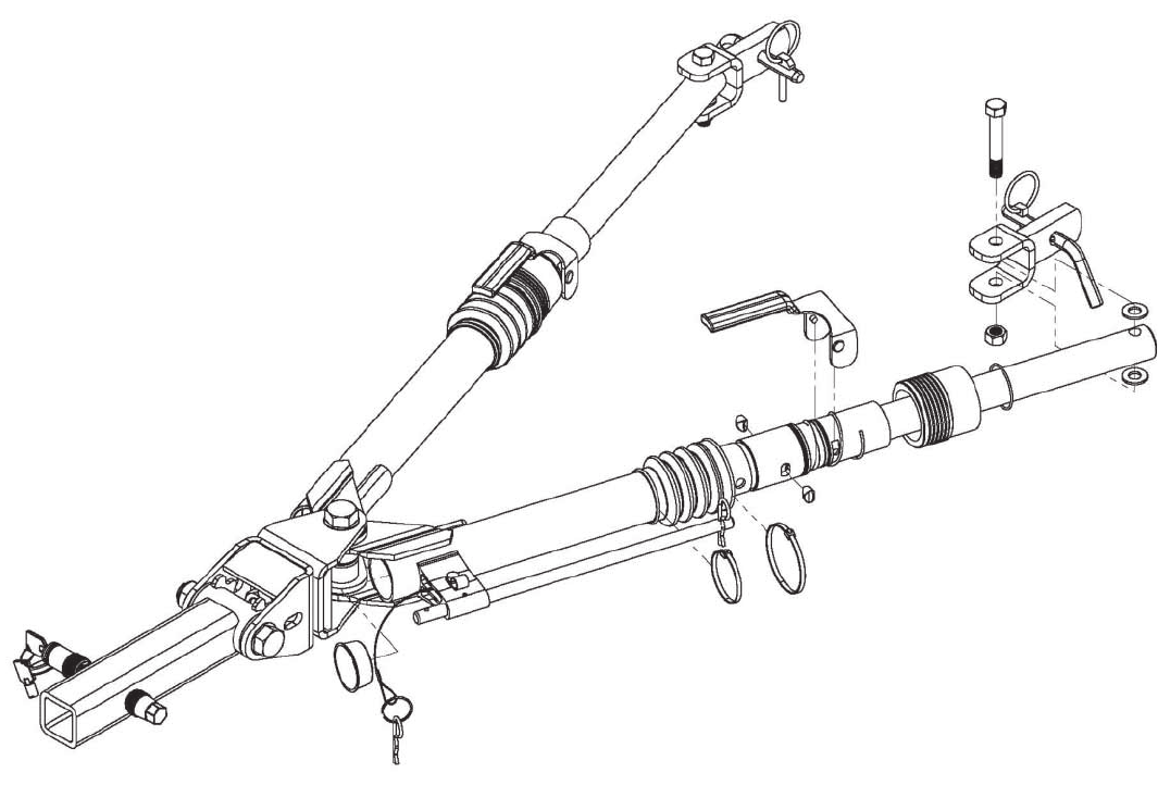
1. Reinstall o-ring (#10) on outer tube. Lubricate only the
o-ring with a lite coat of copper anti-seize (included with
Aluminator
®
Part number 10173). (Note location in Figure
A)
2. Slide rear leg into front connecting leg tube, being carefull
not to damage shaft seal (see Figure A). A slight twisting
motion will aid in the installation. Slide the rear leg in untill
the shaft groove matchess up with the square pawl holes.
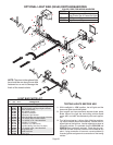
3. Replace the two lock pawls (#11) into the tube insert.
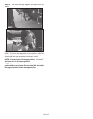
4. Replace Lock Spring (#9) and Lock Collar (#6).
NOTE: The smaller end of the tapered lock spring (#9) must
be against the Lock Insert part of the Front Connecting
Leg.
5. Pull Lock Collar back and slide the rear leg in approximately
halfway. This will hold the Lock Collar in the release posi-
tion.
6. Replace the snap-ring (#8).
7. Replace rubber bellows boot (#14) to lock collar (#6) with
nylon ties (#15).
8. Reattach Connecting Clevis (#3) on Rear Connecting Leg
(#7) with the 1/2” x 3” bolts (#4), washers(#5) and locknuts.
Tighten bolts until clevises are just snug.
9. Reinstall the caplug (#1).
10. Reattach release handle (#13) by tapping on with a rubber
mallet.
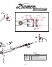
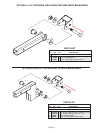
9
10
11
2
1
6
7
8
4
3
5
5
11
12
13
14
15
15