


Page 13
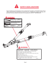
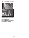
Step 5. Slide and twist the legs into position to attach them
to the baseplate on towed vehicle. Secure to baseplate us-
ing the two attaching pins and 1/4” quick-lock pin. Attach
safety cables (see below). Now connect the lighting cable
between the towing
vehicle and the towed vehicle lighting sys-
tem or optional light bar.
The coiled section of the cable will be
stored on the support rod of the left connecting leg.
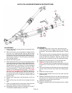
Towing
vehicle must be larger and at least 500 lbs. heavier than
the towed vehicle and tow bar combined.
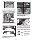
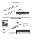
Step 1. Remove safety cables from box and coil a cable
around each leg of the tow bar, starting near the pivot point.
Install the light cable (optional) by placing the coil over the
wire support rod. Secure the cable with the cable anchor
located on left connecting leg lock pin mount. Remove 1/4”
bolt, place anchor over coil of cable and replace bolt. This will
prevent the cable from pulling off and becoming damaged.
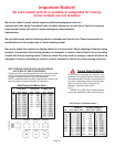
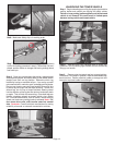
HOOKING UP THE VEHICLE TO BE TOWED
Refer to load limits on inside of front cover.
Step 4. Position the vehicle to be towed approx. 24” behind
the towing vehicle. The vehicles do not have to be in straight
alignment to complete the hook-up. Engage towed vehicle
and towing vehicle parking brake.
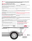
SAFETY CABLE & LIGHT CABLE INSTALLATION
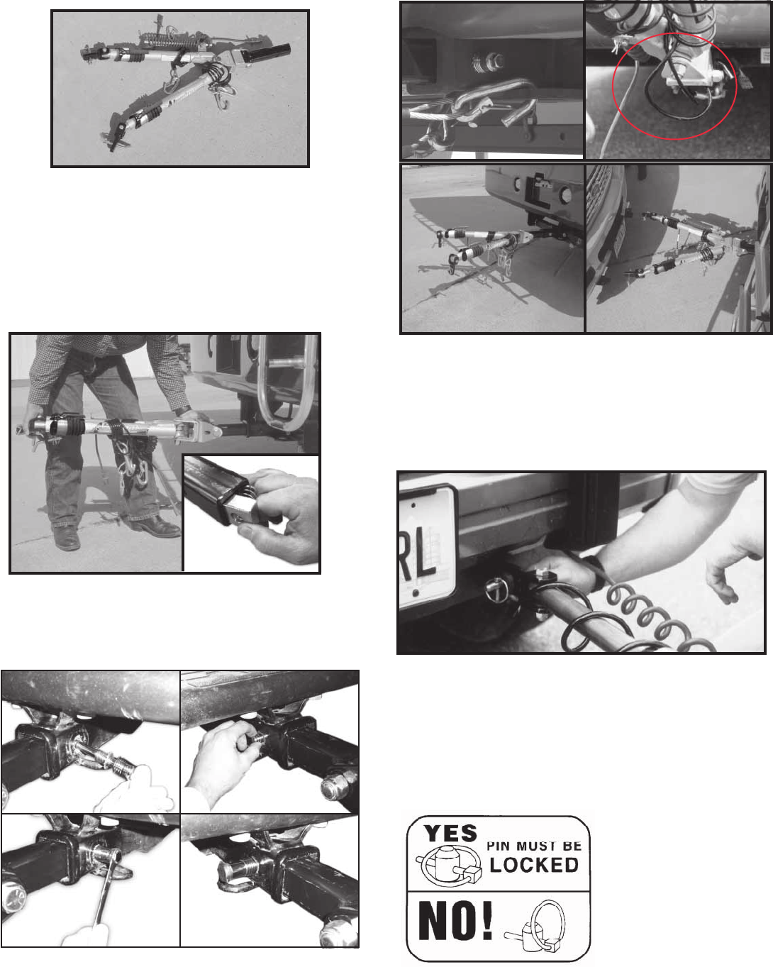
quick-lock pin must be
closed properly. Fold ring
of Quick-Lock Pin to the
side of the pin that allows
ring to snap against pin.
If you have folded its ring
the wrong way it will not
snap against pin.
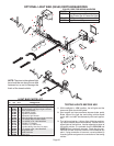
Step 2. Insert the lock pin block and sping into the Alumina-
tor
TM
reciever tube and line up block with hole in tube. Insert
the Aluminator
TM
into a Class III or IV hitch.
Step 3. Insert locking pin with star washer through receiver
on the block side and thread in pin until passes through. Slide
pin bushing over pin and into hitch receiver. Tighten pin use
5/8” wrench and install lock on pin.