


MAN#650302-A
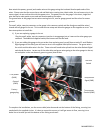
Next attach the power, ground, and sender wires at the gauge using the insulated female spade ends of the
wires. Please note that the sensor has a red and black wire running into a black cable, this red sensor wire is the
sensor signal, do not confuse this with the power wire. The power wire for the gauge is the short, single Red
wire that has a male spade on one end and female spade at the other.
The ground wire at the gauge has two wires coming out of it, one for gauge ground and the other for sensor
ground.
The small, white, two-pin connector on the gauge is the common switch and dim line(green and blue wires)
shared with all gauges in the set. This is used to enter setup and allow the gauges to dim together as a set. You
have two options to install this:
1.) If you are replacing a gauge in the set
Plug the small, white, two-pin connector into the air temp gauge just as it was on the other gauge you
removed. The additional supplied switch/dim harness will not be used.
2.) If you are adding this gauge to the set rather than replacing one (you will have a total of 5 small Dakota
Digital gauges on the bike) you will have to wire in the supplied switch/dim harness. The green wire is
for switch and the blue wire is for dim. These wires will need to be spliced into the other Dakota Digital
switch and dim wires. Locate any of the other blue and green wires going to the other gauges in the set,
cut and splice in the new harness; green to green, blue to blue.
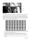
To complete the installation, run the sensor cable/wire down and out the bottom of the fairing, securing it as
needed with the supplied zip ties. It is best to mount the sensor so it will get some air flow, securing it to a
brake line or bracket just out the bottom of the fairing works well.
Factory
gauge plug
+12V power
(PWR)
Ground
(GND)
Temp sensor
Signal (SND)
Temp sensor
Ground (GND)
Dim and
Switch