


INSTALLATION CONSIDERATIONS / WARNINGS
To ease and reduce installation time, we suggest you consider the following points before starting.
1. Determine most suitable locations for all components to be placed. These components include: the
module itself, override / programming switches, and possible relays.
2. Use a Volt-Ohm meter to test and locate all connections.
3. Record all color codes of vehicle wiring to be used for reference. This will save time by not having to
re-test the same wires over again.
4. Allow enough wire to create a service loop with strain relief, should servicing be required. This will
also allow easier access and mounting.
**FOR SAFETY REASONS, DO NOT INSTALL RS700 III/901 in vehicles with MANUAL
TRANSMISSIONS** If accidentally left in gear, a remote started vehicle could become a self-propelled
threat to life and property.
DON'T extend the RS-900 Remote start ignition harness length. Mount the module so that main harness
reaches all ignition switch wiring. Extending these wires could result in poor performance.
DO NOT route any wiring that may become entangled with brake, and gas pedals, steering column, or
any other moving parts in the vehicle.
DO NOT exceed the rated output current of any circuit on the Remote start module. Failure to observe
this warning will result in damage to the unit.
DO NOT remote start the vehicle in a closed garage. Make sure that the garage door is open or there is
adequate ventilation. Failure to observe this rule could result in injury or death from poisonous Carbon
Monoxide fumes.
WIRING INSTRUCTIONS
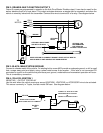
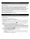
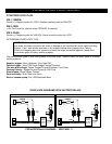
PROGRAM/OVERRIDE SWITCH: 2 PIN PLUG
This switch is used primarily for programming features of the RS700 III/901. However, if the Anti-Grind/Starter
disable feature is installed, you MUST INSTALL this switch. This switch will allow the user to override the starter
disable in the event of a non-operating remote control.
8 PIN PLUG:
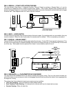
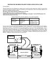
PIN 1: TAN: MULTI-FUNCTION OUTPUT 1
This output comes pre-programmed to provide a ground pulse to disarm the vehicles' FACTORY anti-theft system
prior to ignition on and 2 seconds after start for Defroster activation. This output can also be changed to operate as
a Remote controlled output for trunk release. See Programming Section.
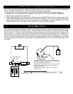
For OEM Disarm: Connect this wire to the vehicles' anti-theft disarm wire. This wire is usually found coming off the
Driver's door key switch or the Factory Anti-theft control module.
For Defroster Activation: Connect this wire to the vehicle's defroster activation switch. It may be necessary to use
a relay. If using both OEM Disarm and Defrost Activation, Use relays to isolate the two circuits from operating
simultaneously, or use diodes to isolate interference.
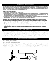
Warning: This system DOES NOT HAVE engine over-rev protection. Make certain
vehicle throttle linkage operates properly and does not stick. A stuck throttle will
cause severe engine damage