


8
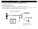
RED WHITE: TACHOMETER INPUT
When installing the system in Tach mode, this wire must be connected to a valid source of AC voltage. This wire allows
the unit to sense the engine running and control the starter motor.
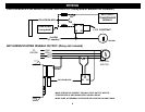
PROGRAM OVERRIDE SWITCH: 2 PIN PLUG (REQUIRED FOR PROGRAMMING & LEARNING REMOTES)
This switch is used for programming features, transmitters, valet mode, and to override the optional starter disable (if
installed) in the event of a non-operating remote control.
LED: 2 PIN PLUG OPTIONAL
The LED is used as a VALET/PROGRAMMING indicator and it will also FLASH for use as security deterrent when the
optional ANTI-GRIND/STARTER DISABLE output is programmed.
VALET / PROGRAM SWITCH
STATUS LED
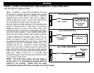
WIRING: 6-PIN HIGH-CURRENT CONNECTOR
BROWN: 12V STARTER OUTPUT 30A:
Connect to circuit in the vehicle that has power ONLY while the STARTER MOTOR is CRANKING.
GRAY: 12V ACCESSORY OUTPUT 30A:
Connect to circuit in the vehicle that provides Accessory Power for systems such as HEAT and A/C. Typically, this wire
turns ON with the first position of the key, DROPS OUT WHEN CRANKING, then returns as the engine starts and runs.
(2) RED: 12V POWER INPUT WIRES (30A Fused):
Connect to both of these leads to 12V Constant Power. We recommend the BATTERY POSITIVE TERMINAL.
PINK: 12V IGNITION OUTPUT 30A:
Connect to circuit in the vehicle that provides true Ignition Power for systems such as Spark and Fuel. Typically, this wire
turns ON with the second position of the key, STAYS ON WHEN CRANKING, and continues ON as the vehicle runs.
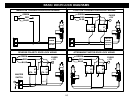
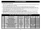
PINK WHITE: 12V MULTIFUNCTION OUTPUT 30A (JUMPER SELECTABLE):
This is an optional multi-function output wire the can be configured as a Second IGN, ACC or STARTER output. Some
vehicles require more than just one IGN, ACC, or STARTER wire in order to start and run successfully. If this is the case
for your particular vehicle, then use the jumper pin located under the access panel on the top of the CoolStart control
module to configure this wire to suit your needs. The DEFAULT setting is IGNITION. See Jumper Pin Diagram page 24.