


3
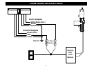
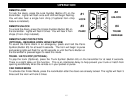
COMPONENT MOUNTING
CONTROL MODULE: Locate the module underdash as high as possible. Driver’s Side usually provides an
easy location for the majority of the wiring connections. The antenna wire should be routed away from any
metal if possible. DO NOT alter the length of the antenna wire, or ground the antenna wire.
PROGRAM BUTTON: Mount the button in a hidden but accessible location. It is used for programming new
remote controls.
LED (Optional): The optional Red LED provides a useful theft deterrent. The LED blinks after you lock the
vehicle with your remote simulating an alarm system. The LED is also used when programming remotes. If
you decide to install the LED, choose a visible location in the dash or console for a location.
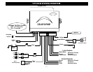
WIRING
YELLOW WIRE: IGNITION SWITCHED “ON” AND “START” +12 VOLTS
Connect to an ignition wire that shows +12 Volts when the key in both “On” and “Start” positions.
BROWN/BLACK: (-) HORN HONK/CHIRP OUTPUT (Optional, requires relay)
This wire provides a negative pulse output to honk/chirp the factory horn for audible lock/unlock confirmation.
Connect Brown/White to terminal 86 of a relay. Connect terminal 85 to +12V Constant. Connect terminal 87
to +12V or GROUND depending on the type of horn activation circuit in the vehicle. Connect terminal 30 to
the horn activation circuit. NOTE: Many vehicles use a Negative type of horn circuit, however we recommend
that you test the circuit on your vehicle before making any connections to avoid any possible damage.
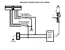
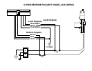
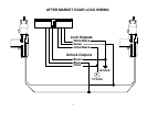
BLACK WIRE: SYSTEM CHASSIS GROUND
THIS WIRE MUST BE CONNECTED TO CHASSIS METAL OF THE VEHICLE. Scrape away any paint or dirt
from the connection point to ensure a good connection. Keep ground wire short.
GRAY WIRE: (-) AUXILIARY REMOTE OUTPUT 1 (Optional, requires relay)
Negative Pulsed output controlled by pressing Button #3 (Trunk Symbol) for at least 1 second.