


CON 2
15 16
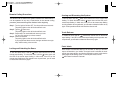
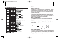
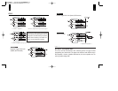
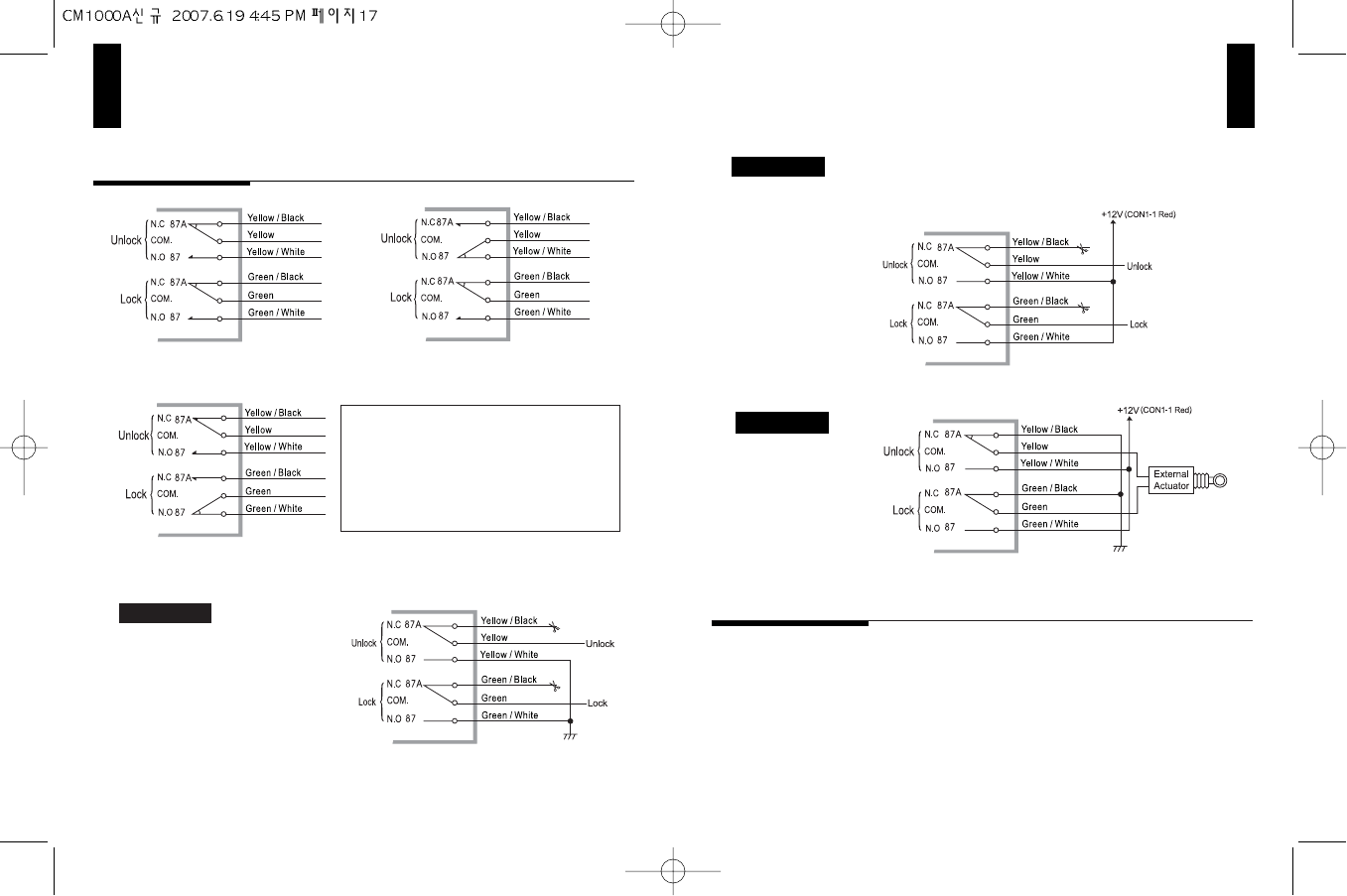
< Circuit diagram >
<Circuit diagram during unlock output >
<Circuit diagram during lock output >
The lock and unlock outputs of the CM1000A
are actually two pre-wired relays that can be
configured in the three following ways listed
below. When connecting to a constant 12v+
source, you must fuse the connection.
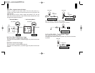
Negative Trigger Door Lock
System (W/O Actuator)
Positive Trigger Door Lock System (W/O Actuator)
< External Actuator >
External Actuator
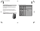
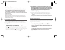
No.1 Green : (+)12v Ignition Input
This wire must be connected to the vehicles ignition to trigger remote
programming and Valet mode. The proper wire will test 0-volts with the key in
the off position, 12-volts (+)positive while the key is in the on position and 12-
volts (+) positive during crank.
Method 1
Method 2
Method 3
CON 3