


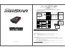
CM4200DX Remote Starter
INSTALL GUIDE
WWW.COMPUSTAR.COM
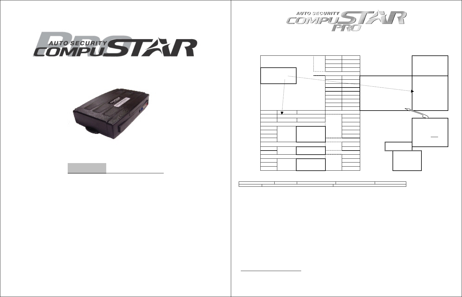
CM4200 Alarm/Starter Control Module
This manual is for professional installers. Please read and understand this manual before you start to install.
If you have any questions, please do not hesitate to call the tech support (888)820-3690. ( 8 am to 5 pm Pacific Time)
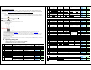
I. Wiring Chart and Notes
1 Red 2 Gr/Wht 1: ( + ) 12v Constant 2: ( + ) Parking Light
3 Red/Wht 4 White 3: ( + ) 12v Constant 4: ( + ) Accessory
5 Violet 6 Yellow 5: ( - ) When Armed 6: ( + ) Starter
CN1
7 Gr/Red 8 Black 7: ( + ) Ignition 8: ( - ) Ground
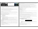
Note 5: If the vehicle uses a
negative parking light circuit, you
can use the positive parking light
wire on this harness as a positive
trunk release output by changing
one of the onboard jumpers below.
1 Grn/Wht 2 Lt Blue 1: ( - ) Parking Lt. Output POC #1 2: ( - ) E-Brake Input
Note 1. CN3 #10 input can be
programmed either Glow Plug
(default) or Key Sensing. Option 4-
9. Then, you can select either + or
– input with the dipswitch.
3 Red/Blk 4 Lt. Blue/Wht 3: ( - ) Starter Output POC #2 4: ( + ) Brake Input
5 Green 6 Violet/Blk POC #3 POC #3 6: ( - ) Trunk Input
7 Wht/Blk 8 Red/Wht POC #4 POC #4 8: ( - ) Door Input
9 Black 10 Brown/Wht 9: ( - ) Status Out (GWR) POC #5 10: ( - ) Key Sense/Glow Input
Jumper
Cut=Auto / Uncut=Manual
11 Orange 12 Dark Org 11: ( - ) Rearm Output POC #6 12: ( - ) Slave/Timer Start Input
13 Org/Wht 14 Yel/Blk POC #7 POC #7 14: (AC) Tach / Alternator Input
15 White 16 Gray/Blk POC #8 POC #8 16: ( - ) Hood Input
CN3
17 Violet 18 Brown POC #9 POC #9 18: ( + ) Siren Output
Dipswitch (+) Door Trigger (-) Door Trigger
Dipswitch Glow Plug/Key-sense Polarity 1 Black Future use
Dipswitch ( + ) Trunk ( + )Parking Light 2 Violet/Wht ( - ) Trunk release output
3 Orange/Blk ( - ) Second Unlock Output
4 ( - ) 4 Blue ( - ) Unlock Output
3 ( + ) 5 Blue/Blk ( - ) Lock Output
All outputs in
CN3 and CN4
are 250 mA.
2 Data
CN4
6 Red ( + ) 12v Constant Power
1 Data
CN12
RS232
Note: 2. This port is used
for firmware updates and to
connect to bypass modules.
Black LED ( - )
Note 6: POC stands for
Programmable Output Connectors.
Each one of these 9 outputs can be
configured to one of the 12 outputs
as detailed later in this manual.
However, if you want to use the
channel expander, you have to
configure CN3-17(POC #9
) to Aux
1 and connect POC #9 to the data
wire of the channel expander.
Then, set up the options on 3-11
and 3-12.
1 Thermistor
CN5
LED
Black/wht LED ( + )
Note 7. LED is optional
on all systems.
2 Thermistor
CN11
Thermistor
Note 3: Thermistor is
optional on 2WLED and 1
Way sets.
1 Black ( - )
( - ) Switch 3 gray 2 White ( + )
( + ) Led 2 Gray 3 Red Tx
( - ) Led 1 Gray/Black
CN9
Plug In LED
Switch
Note 4. Used for firmware
updates and secure valet.
Option 3-10.
CN8
Antenna
4 Yellow Rx
Note 8: Tach Learning and
Engine Sensing have been
changed. See Option 2-10.
Note 9. Whenever the system fails to remote start, the vehicle provides you Diagnostic Error Messages: # of times parking lights flash. (2 Way LCD Remotes will show Strt Er##.)
1 - Engine On 2 - Key On 3 - Door Open 4 - Trunk Open 5 - Foot Brake On
6- Hood Open 7 -Reservation Off (Manual Transmission Only) 8 – No Tach or Voltage Sensing Failure
___________________________________________________________________________________________________
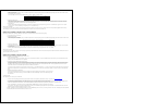
Note 10: Additional Items to Install
Antenna Usually mounted in the front windshield. Stay at least 1.5 inches away from metal and mount below the tint stripe.
LED Switch Enables the use of Secure Valet mode, mount where the customer will have convenient access.
LED Theft deterrent, LED output is 3 volts.
Thermistor Senses the current temperature, this item is connected to a port on the back side of the controller.
___________________________________________________________________________________________________
Note 11: Remote Coding Procedure
To code the remote to the system you must have; both 12v+ constant wires, the ground wire, and the ignition wire of the system connected to the vehicle. You must have the antenna connected to the main
controller as well. After you have connected these wires or more, follow these steps to code a remote to the system. Please read through the steps before beginning.
1. Cycle the key in the ignition from the “Off” position to the “On” position 5 times. This must be done within 5 seconds. The 5
th
time you turn the ignition on, you will hear the parking light
relay “click”. This will happen the moment the ignition is turned on the 5
th
time so it is easy to miss the first relay click. If you hear two relay clicks, the system has just exited remote
coding mode.
2. Right after cycling the ignition for the 5
th
time and receiving the first relay click:
a. 1-Way Remote: Tap the lock button on the remote for 0.5 seconds.
b. 2-Way Remote: Tap button I for 0.5 seconds
3. After pressing the button on the remote, you will hear the parking light relay click once to indicate that it has accepted the remote. If you have other remotes to program to the system, repeat
step 2 for each remote you have, one after the other. Each system can accept three remotes with the exception of the SS Pro.
Remote Coding – under Secure Valet – Option 3-10-III
If you elect Option 3-10-III, you can code remotes when you put the system into Secure Valet. Upon entering the secure valet code, you will hear the parking light relay click. Program a remote or remotes
until you hear two relay clicks. See the note later in this manual regarding Secure Valet, Option 3-10.