


© 2006, Chamberlain Group Inc.
114A1137C All Rights Reserved
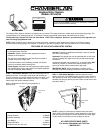
NOTE: If your garage has a built up jamb, drill the hole 2" deep.
Then, on inside edge of jamb, drill a second hole into first hole to
complete access.
STEP 2: Hold keyboard firmly with the back of the case UP.
Position thumb against bottom of case and pull up sharply.
Keyboard will lift out of cover, allowing access to bottom
mounting hole.
Guide the keyboard cable through hole to inside th
e garage.
Position the keyboard against outside jamb. Drill two 1/8" pilot
holes for fastening screws. Attach securely with (2) 6ABx1-1/4"
screws. Close cover.
Excess cable can be folded and inserted into the access hole to
keep it o
ut of the way.
STEP 3: Connect the 2-strand bell wire to terminals labeled 1
and 2 on back of co nsole. Insert keyboard cable connector into
slot on side of console. Be sure connector guides are facing
BACK of console.
IMPORTANT: Some garage door openers have a third screw
terminal which supplies power to the radio control. This terminal
can be connected to terminal No. 3 on the console with a third
strand of bell wire (not supplied).
With any garage door opener made by Stanley, accessory
Transformer 95 MUST be Installed.
TRANSFORMER INSTALLATION INSTRUCTIONS
Connect one end of the 2-strand bell wire supplied with the kit to
each of the transformer terminals (no polarity). Connect the oth
er
end of bell wire to terminals 1 and 3 on the Keyless Entry
console.
If this accessory is used with any garage door opener other than
Sears or Chamberlain and the battery fails in two months,
transformer must be insta
lled. Follow Instructions above.
STEP 4: Position console on an interior garage wall
approximately one foot from outside edge of door. Fasten
with (2) screws provided.
Run bell wire up wall and across ceiling to garage door
opener terminals. Use insul
ated staples to secure wire. On
current line Chamberlain models, connect wire to red and
white opener terminals. On older models, connect to
terminals used for push button controls. Cut off any excess
wire. Connect to t
erminals used for push button
controls.
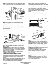
STEP 5: Pry open front panel of console with a coin or
screwdriver. Snap a 9 volt battery onto circuit board
connector and drop into console. DO NOT replace panel at
this time.
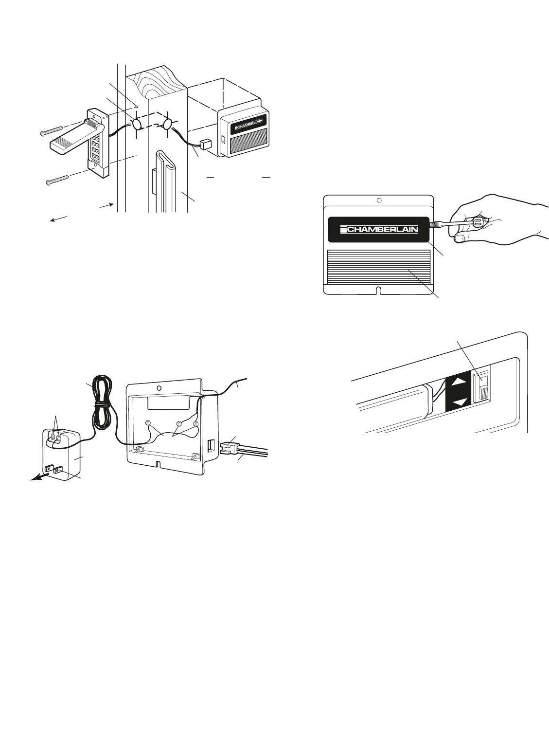
STEP 6: To set code, move program/operate switch near
the battery to PROGRAM position (keyboard light should
flash).
NOTE: If the light does not flash, check the cable and
battery connections. Press any four numbers on keyboard.
CAUTION: For security, do not use address, license or
consecutive numbers (1,2,3,4 etc.).
Move the program/operate switch to OPERATE position
(the keyboard light will go o
ff).
Reconnect power to garage door opener.
NOTE: If you have Installed Transformer Model 95, plug
the transformer Into a 120 VOLT outlet.
Enter the code on the keyboard. If the door operates
properly, replace the front panel on the console.
Loss of power to either the battery or th
e garage door
opener will not affect the programmed code. However, if
BOTH lose power, the code must be reset.
Battery should produce adequate power for at least one
year. If light In keyboard does not turn on, cha
nge the
battery.
NOTE: To maintain the privacy of your code, keep all of
the buttons free from soil. If any of the numbers show
signs of wear, change your code.
1/8" Pilot Hole
1" Dia. Hole
2" Deep
6ABx1-1/4"
Screw
Door
Opening
Cable
Inside
Garage Wall
Inside Edge
of Jamb
Console
Front
Panel
Console
Push Button
Program/Operate
Switch
Battery
PROGRAM
OPERATE
Bell Wire
Transformer
Terminals
Transformer
Model 95
Console
Terminals
To 120V Outlet
Cable
Bell Wire
(To Garage
Door Opener)
Connector
Guides
3
21