


(4)
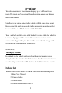
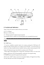
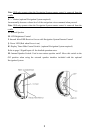
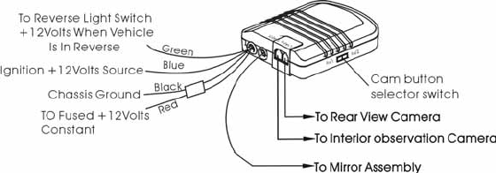
Electrical Connections: Connect the 4 wires in the following manner.
a) Red wire - 12 volt constant (positive)
b) Black wire - Chassis ground (negative)
c) Blue wire - 12-volt ignition (12 volt with ignition on)
d) Green wire - Reverse light switch (12 volt when vehicle is in the reverse gear)
WARNING: Observe polarity when connecting the wires.
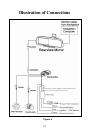
Figure 2
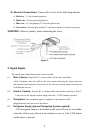
2. Signal Inputs
The signal input connections for the system include:
(1)
Rear Camera: Plug the RJ 11 camera cable end into the control box
AVin-1 location, route the cable to the rear camera and plug the 4-pin connector
into camera 4 pin connector. Users can see the rearview camera image when the car
is shifted into reverse.
(2) Interior Camera:
Plug the RJ 11 camera cable end into the control box AVin-2,
Users can see the interior camera image when the “CAM” button is pressed.
(3) Navigation: The navigation signal is supplied via the monitor cable
plugged directly into the rear of the mirror.
(4) Navigation Image (optional Navigation System required)
The Navigation Image is the default mode, and will only be overridden
when the vehicle gear selector is moved into reverse, or if the CAM button
on the mirror is pressed.
5