


GB
GB
1
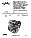
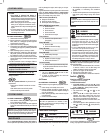
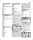
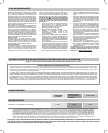
DIESEL ENGINE COMPONENTS
Models 432447, 522447 and 582447
Fig. 1
1
Engine ID. Label: Model, Type & Code Numbers
Note: See ENGINE IDENTIFICATION NUMBERS−
last section
2
Injector Nozzle
3
Oil Filler Cap
4
Glow Plug
5
Oil Drains
6
Oil Filter
7
Dipstick
8
Injector Pump
9
Electric Starter
10
Alternator
11
Oil Pan
12
Thermostat
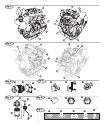
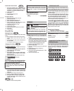
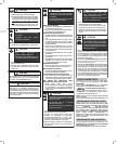
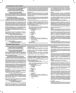
TURBOCHARGED DIESEL ENGINE
COMPONENTS
Models 588447 and 58A447
Fig. 2
1
Engine ID. Label: Model, Type & Code Numbers
Note: See ENGINE IDENTIFICATION NUMBERS−
last section
2
Injector Nozzle
3
Oil Filler Cap
4
Glow Plug
5
Oil Drains
6
Oil Filter
7
Dipstick
8
Injector Pump
9
Turbocharger
10
Electric Starter
11
Alternator
12
Oil Pan
13
Thermostat
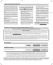
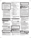
ADDITIONAL COMPONENTS
Air Cleaner Assembly
Fig. 3
1
Body
2
Cartridge
3
Cover
4
Clamps
Fuel Filter Assembly
Fig. 4
1
Sensor Wire
2
Water Drain Valve
3
O-Ring
4
Fuel Filter
5
Priming Pump
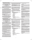
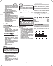
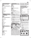
PANEL COMPONENTS
Typical Controls (if equipped)
Fig. 5
1
Fuel Shut-off Valve
2
Throttle
3
Starter Switch
Typical Gauges (if equipped)
Fig. 6
1
Fuel gauge
2
Coolant Temperature Gauge
3
Hour Meter − Indicates total number of hours the
engine has been run.
Typical Panel Lights (if equipped)
Fig. 7
Lights will illuminate when the starter switch is turned to ON
position, and should be out while engine is running.
CHECK ENGINE IF LIGHTS TURN ON DURING
OPERATION.
1
Heat or Glow Light − The heat or glow light
comes on when the key is turned to HEAT or
GLOW. If no HEAT or GLOW position, it will light
in ON position.
2
Engine Oil Pressure Light − If illuminates during
engine operation, shut down engine immediately.
Check oil level, or electrical system.
3
Charge Light − If illuminates during engine
operation, check electrical system.
4
Fuel Filter Light − Illuminates when enough
water collects in the fuel filter, but should be out
when the water is drained.
5
Temperature Light − If illuminates during engine
operation, engine is overheating. Check coolant
level; check for debris on radiator or any restric-
tion to air flow.
INTERNATIONAL SYMBOLS
SHOWN ON ENGINE
On Off
Read Operating and
Maintenance Instructions
Stop
Fuel
Safety Alert
Oil
Slow
Fast
TECHNICAL INFORMATION
Engine Power Rating Information
The gross power rating for individual gas engine models is
labeled in accordance with SAE (Society of Automotive
Engineers) code J1940 (Small Engine Power & Torque Rating
Procedure), and rating performance has been obtained and
corrected in accordance with SAE J1995 (Revision 2002-05).
Torque values are derived at 3060 RPM; horsepower values
are derived at 3600 RPM. Actual gross engine power will be
lower and is affected by, among other things, ambient
operating conditions and engine-to-engine variability. Given
both the wide array of products on which engines are placed
and the variety of environmental issues applicable to operating
the equipment, the gas engine will not develop the rated gross
power when used in a given piece of power equipment (actual
on-site" or net power). This difference is due to a variety of
factors including, but not limited to, accessories (air cleaner,
exhaust, charging, cooling, carburetor, fuel pump, etc.),
application limitations, ambient operating conditions (temper-
ature, humidity, altitude), and engine-to-engine variability. Due
to manufacturing and capacity limitations, Briggs & Stratton
may substitute an engine of higher rated power for this Series
engine.
ENGINE SPECIFICATIONS
3-Cylinder, Liquid Cooled Diesel Engine
THIS ENGINE IS CERTIFIED TO OPERATE ON
DIESEL FUEL.
Model 432447
Bore 68 mm (2.68 in.). . . . . . . . . . . . . . . . . . . . . . . . .
Stroke 64 mm (2.52 in.). . . . . . . . . . . . . . . . . . . . . . .
Displacement 697 cc (42.5 cu. in.). . . . . . . . . . . . . . .
Model 522447
Bore 68 mm (2.68 in.). . . . . . . . . . . . . . . . . . . . . . . . .
Stroke 78 mm (3.07 in.). . . . . . . . . . . . . . . . . . . . . . .
Displacement 850 cc (52.0 cu. in.). . . . . . . . . . . . . . .
Model 582447, 588447, 58A447
Bore 72 mm (2.83 in.). . . . . . . . . . . . . . . . . . . . . . . . .
Stroke 78 mm (3.07 in.). . . . . . . . . . . . . . . . . . . . . . .
Displacement 953 cc (58.1 cu. in.). . . . . . . . . . . . . . .
SAFETY SPECIFICATIONS
WARNING
THE OPERATING & MAINTENANCE IN-
STRUCTIONS CONTAIN SAFETY INFORMATION TO
• Make you aware of hazards associated with
engines.
• Inform you of the risk of injury associated with
those hazards, and
• Tell you how to avoid or reduce the risk of injury.
The safety alert symbol
is used to identify safety
information about hazards that can result in personal injury.
A signal word (DANGER, WARNING, or CAUTION) is
used with the alert symbol to indicate the likelihood and the
potential severity of injury. In addition, a HAZARD SYM-
BOL may be used to represent the type of hazard.
DANGER indicates a hazard which, if not
avoided, will result in death or serious injury.
WARNING indicates a hazard which, if not
avoided, could result in death or serious injury.
CAUTION indicates a hazard which, if not
avoided, might result in minor or moderate injury.
CAUTION, when used without the alert symbol,
indicates a situation that could result in damage
to the engine.
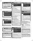
Hazard Symbols
Explosion
Toxic Fumes
Shock Hot Surface
Fire
Hot liquid or
Steam
Moving Parts